


6-53
Cisco MGX 8850 Multiservice Switch Installation and Configuration
Release 1.1.31, Part Number 78-11223-03 Rev. B0, May 2005
Chapter 6 Card and Service Configuration
Eight-Port Circuit Emulation Service Modules
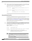
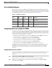
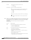
Error and Alarm Response
When it detects a loss of signal (LOS) alarm, the CESM notifies the connected CPE in the upstream
direction after an integration period. The CESM continues to emit cells but sets the ATM cell payload
with an appropriate data pattern as specified by the ATM Forum CES V2.0 specification. Also, an OAM
cell with RDI code goes to the far end to indicate out of service. See (Table 6-5).
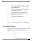
Configuring Service on an Eight-Port CESM
This section describes the steps for setting up a CESM and adding connections. The maximum number
of connections is 248 on the MGX-CESM/B-8E1 and 192 on the MGX-CESM/B-T1. Use either the CLI
or the Cisco WAN Manager application to set up a CESM and add connections. The following list shows
the fundamental tasks and applicable CLI commands:
• Optionally configure redundancy at the card level (addred and possibly addlink on the PXM1)
• Optionally modify resource partitions at the card level (cnfcdrscprtn)
• Activate a physical line (addln) and optionally configure the line (cnfln)
• Create logical ports for structured data transport on a physical line (addport)
• Optionally modify resource partitions at the port level (cnfportrscprtn)
• Add connections by using addcon (or addchan if NSAP addressing is necessary)
For CESM-related commands, see the list of service module commands at the beginning of the Cisco
MGX 8800 Series Switch Command Reference. Also, each command description in the command
reference lists related commands. For example, it shows display commands that relate to addition
commands.
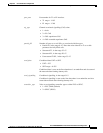
Configuring the Card, Lines, and Ports
This section describes how to configure parameters for the card, lines, and ports through the CLI. If you
use the CiscoView application, refer to the CiscoView documentation. On the CLI, the command
sequence is:
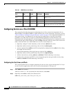
Step 1 Add the line by entering the addln <line number> command.
where line number is in the range 1–8. You can modify line characteristics with cnfln.
Step 2 Optionally execute cnfln to modify line characteristics from the defaults. (Use dspln or dsplns to
check). The syntax for cnfln is:
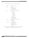
Table 6-5 CESM Errors and Alarms
Error
Alarm
Type
Down
stream Up Stream Comments
Link Failure
(RX)
Blue (LOS) AIS—OAM
cells
none Data cells According to ATM-Forum
CES-IS V 2.0
Receive RAI Yellow None None —
Receive LOF — — — —
Receive AIS Blue (AIS) AIS (link) FERF OAM
cells
AIS over the T1 link or alternating 1s
and 0s E1 link.