


4-30
Cisco MGX 8850 Multiservice Switch Installation and Configuration
Release 1.1.31, Part Number 78-11223-03 Rev. B0, May 2005
Chapter 4 Enclosure and Card Installation
Initial Start-up of the MGX 8850
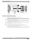
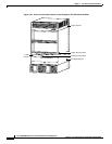
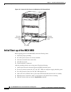
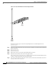
Figure 4-27 Access for Fan Power at the Backplane, DC-Powered Node
Initial Start-up of the MGX 8850
Before applying power to the MGX 8850, check the following items:
1. Switch has proper grounding.
2. AC or DC power sources are correctly installed.
3. All cards are locked in the correct slots.
4. All cables are secure.
5. Control terminal is connected.
After the preceding checks, turn on the power. Check the following:
1. At the front of the unit, the status light on the PXM1 should be green.
2. For an AC-powered system, the “AC” and “DC” LEDs on each power supply should be green.
3. For a DC-powered system, the “DC OK” LED should be on.
4. After each service module comes up, the status LED should show that the card is in standby.
5. When the power is turned on, make a visual check to verify that all fans are running.
6. After the system comes up, enter the dspshelfalm command.
17677
DC power
interconnect
cable
DC power
interconnect
cable
DC PEMs