


A-17
Cisco MGX 8850 Multiservice Switch Installation and Configuration
Release 1.1.31, Part Number 78-11223-03 Rev. B0, May 2005
Appendix A System Specifications
MGX-FRSM-HS2 Specifications
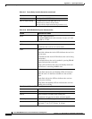
E3 Framer Level
For line framing, the E3 operation of the MGX-FRSM-2T3E3 complies with G.751.
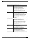
MGX-FRSM T3 and E3 Line Alarms
For line alarms, the MGX-FRSM-2T3E3 supports:
• Detection and generation of Remote Alarm Indicator (RAI) signal (also known as FERF and Yellow
signal)
• Detection and generation of Alarm Indication Signal (AIS)
• Detection of Out Of Frame (OOF) condition
• Detection of Loss Of Frame (LOS) condition
• Automatic generation of Far End Block Error (FEBE)
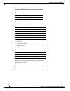
Statistics and Counter Specifications
For lists of applicable statistics and counters, “Counters and Statistics for FRSM-VHS Cards” in this
appendix.
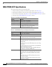
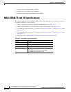
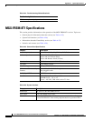
MGX-FRSM-HS2 Specifications
The MGX-FRSM-HS2 is the Frame Relay module with two HSSI ports. The topics in this section are:
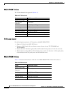
• Transport technology standards with which the card complies. (See Table A-17.)
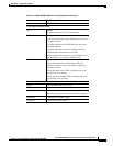
• General physical attributes of the card, such as LEDs on the faceplate. (See Table A-18.)
• Line and framer characteristics. (See Table A-19.)
For lists of the counters and statistics that are available on the MGX-FRSM-VHS series of cards, see
“Counters and Statistics for FRSM-VHS Cards” in this appendix.
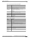
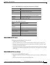
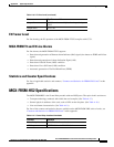
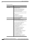
Output Jitter 0.05 UI maximum with jitter-free input clock per
G.823
Output Pulse Per G.703
Table A-16 E3 Line Level (continued)
Feature Significance or Value
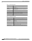
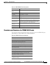
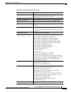
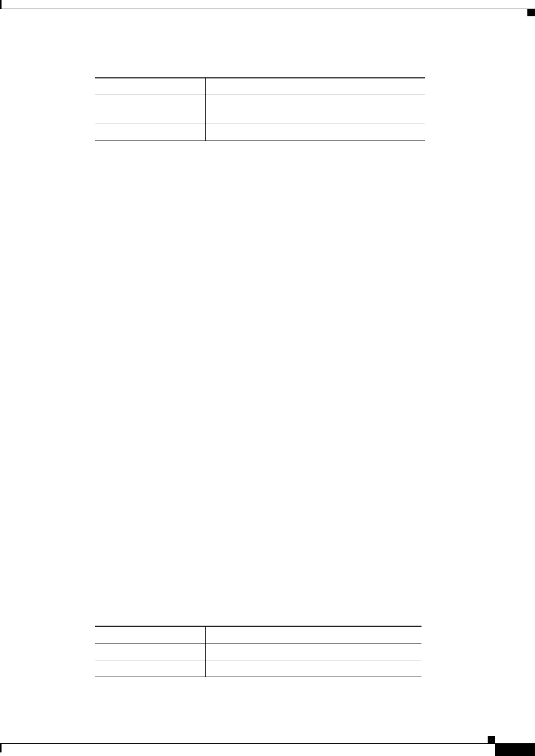
Table A-17 Frame Relay Interface Standards
Interface Standard
Frame Relay Interface ANSI T1.618, 2-octet header
ATM Layer CCITT I.361 and ATM UNI v3.1