


4-25
Cisco MGX 8850 Multiservice Switch Installation and Configuration
Release 1.1.31, Part Number 78-11223-03 Rev. B0, May 2005
Chapter 4 Enclosure and Card Installation
Install System Power Cables
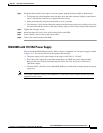
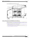
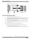
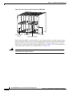
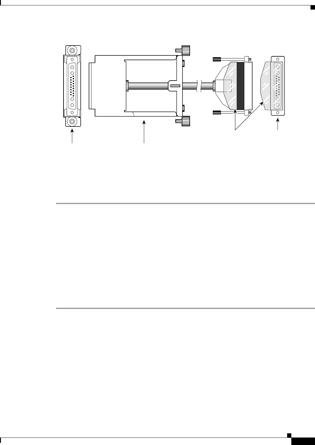
Figure 4-22 Cable Assembly for System Power
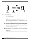
Steps to Install System Power Cabling
Perform the following steps to install the system power cabling.
Step 1 With the narrow row of pins in the D-connector on the bottom, use two hands to slip the larger connector
through the access hole at the base of the card cage.
Step 2 Move the connector straight toward the backplane so you can guide it through the second, internal guide.
When you have fully seated the D-connector in the backplane connector, the captive screws on the frame
are clearly aligned with the threaded holes on the chassis.
Step 3 Tighten the captive screws only enough to secure the connector. Do not apply much torque. Do not use
a power screw driver.
Step 4 Insert the D-connector without the frame in J1 on the power assembly
Step 5 Tighten captive screws only enough to secure the connector. Do not use a power tool.
If you need to swap a DC PEM in a redundant system with the power on, see the ““Redundancy for
Service Modules” section on page 1-10 for instructions.
17675
Connector frameTo backplane
To DC PEM
DO NOT REMOVE
CONNECTOR BAND OR COVER
Plastic cover
(only on DC systems)