


2-46
Cisco MGX 8850 Multiservice Switch Installation and Configuration
Release 1.1.31, Part Number 78-11223-03 Rev. B0, May 2005
Chapter 2 Module and Service Descriptions
Frame Relay Service Modules
• A single T1/E1 CESM card can provide standby redundancy for all active CESM cards of the same
type in the shelf (N:1 redundancy), with SRM.
• CESM cards are supported by standards-based management tools, including Simple Network
Management Protocol (SNMP), Trivial File Transfer Protocol (TFTP) for configuration and
statistics collection, and a command-line interface. Cisco WAN Manager also provides full
graphical user interface (GUI) support for connection and equipment management.
1:N Redundancy for the CESM T1/E1
Redundancy for the AX-CESM-8T1 and AX-CESM-8E1 is available through the MGX-SRM-3T3/C.
• 1:N redundancy requires that the group contain one redundancy back card.
• The redundancy back card must be the special R-RJ45 version (AX-R-RJ48-8T1-LM or
AX-R-SMB-8E1-LM).
For information on installation requirements, see the “Service Resource Module” section on page 2-12.
For configuration requirements, see the “Service Resource Module” section on page 6-60.
For instructions on how to use the CiscoView application to configure redundancy, refer to the
CiscoView user-documentation.
Card Combinations
A card set has an AX-CESM-8T1 or AX-CESM-8E1 front card and one of the following back cards:
• AX-RJ48-8T1-LM
• AX-R-RJ48-8T1-LM (for redundancy support)
• AX-RJ48-8E1-LM
• AX-SMB-8E1-LM
• AX-R-SMB-8E1-LM (for redundancy support)
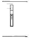
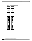
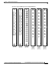
CESM T1/E1 Illustrations
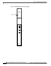
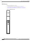
• Figure 2-24 on page 2-48 shows the front cards for the Eight-Port CESM (T1 and E1).
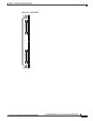
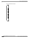
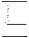
• Figure 2-25 on page 2-49 shows the RJ-48 and SMB Back Cards for the MGX-CESM-8T1E1.
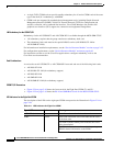
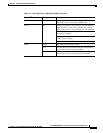
LED Indicators for the Eight-Port CESM
The description of the LEDs on the eight-port CESM correspond to the illustration in Figure 2-24 on
page 2-48.
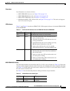
Table 2-11 LED Indicators for Eight-Port CESM
Type of LED Color Meaning
ACT LED (Active) Green On indicates the card set is in active mode.
STBY Yellow Slow blink without the active LED indicates the card is
in the boot state.
Fast blink with the standby LED indicates the card is
being downloaded.
Fast blink indicates the service module is passing
BRAM channel information to the PXM1