6-40
Cisco MGX 8850 Multiservice Switch Installation and Configuration
Release 1.1.31, Part Number 78-11223-03 Rev. B0, May 2005
Chapter 6 Card and Service Configuration
Configuring Frame Relay Service
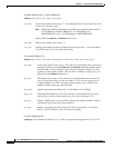
Step 2 Modify a connection as needed by executing cnfcon. See the command line Help or the command
reference for the parameters for individual card types.
Step 3 If necessary, modify the CLP and congestion indicator fields by using cnfchanmap. Use dspchanmap
to check this configuration for a connection.
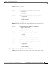
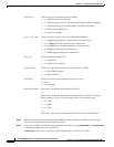
cnfchanmap <chan_num> <chanType> <FECN/EFCI> <DE to CLP> <CLP to DE>
channel type Value to set type of connection on this channel.
• 1 = NIW (network interworking)
• 2 = SIW-transparent (service interworking without any SDU translation)
• 3 = SIW-translation (service interworking with SDU translation)
• 4 = FUNI (Frame Relay UNI)
• 5 = frame forwarding
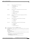
egress service type Value to set type of egress service provided on this channel.
• 1 = highpriorityQ (typically committed bit rate connections)
• 2 = rtVBRQ (real-time variable bit rate connections)
• 3 = nrtVBRQ (non-real-time variable bit rate connections)
• 4 = aBRQ (available bit rate connections)
• 5 = uBRQ (unspecified bit rate connections)
Adm_cntrl Value to enable or disable CAC.
• 1 = enable CAC
• 2 = disable CAC (default)
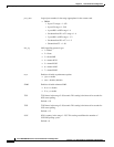
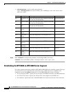
controller_type Value to set signalling controller type as either PVC or SPVC.
• 1 = PVC (PAR) (default)
• 2 = SPVC (PNNI)
mastership Value to set status of the connection as master or slave.
1 = master
2 = slave (default)
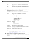
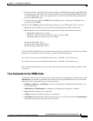
RemoteEndConID Node name, slot number, port number, and DLCI.
or
Node name, slot number, port number, Controller ID, and DLCI for a Frame
Relay endpoint. Use one of the following values to set controller type:
• 0 = PAR
• 1 = PNNI
• 2 = TAG
or
Node name, slot number, port number, and VPI.VCI for an ATM endpoint.


