


B-10
Cisco MGX 8850 Multiservice Switch Installation and Configuration
Release 1.1.31, Part Number 78-11223-03 Rev. B0, May 2005
Appendix B Cabling Summary
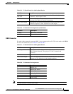
External Alarm Cabling
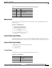
External Alarm Cabling
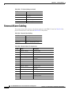
The external alarm cable connects to the Alarm connector on the PXM1-UI card. See Table B-19 for
physical characteristics of the cable and Table B-20 for the pinouts.
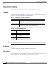
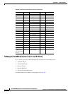
4 Rx ring in
5 Rx tip in
6 No comment
7 Test point ring out
8 Test point tip out
Table B-18 7T1 Clock Cabling (continued)
Pin No. Name
Table B-19 External Alarm Cabling
Cable Parameter Description
Interface Dry-contact relay closure.
Wire 24 AWG, shielded, 6-pair.
Connector DB-15, subminiature, male.
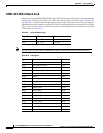
Table B-20 Network Alarm Pin Assignments
Pin No. Alarm Description
1 Audible—Major Normally open
2Common
9 Normally closed
4 Visual—Major Normally open
5Common
12 Normally closed
7unused n.c.
8unused n.c.
3 Audible—Minor Normally open
11 Common
10 Normally closed
6 Visual—Minor Normally open
14 Common
13 Normally closed
15 unused n.c.