


4-46
Cisco CRS-1 Carrier Routing System 8-Slot Line Card Chassis Installation Guide
OL-6256-08
Chapter 4 Installing and Removing MSCs, PLIMs, and Associated Components
How to Install or Remove a Physical Layer Interface Module (PLIM)
Steps
To remove the PCMCIA card, follow these steps:
Step 1 Attach the ESD-preventive wrist strap to your wrist and connect its leash to an ESD connection socket
on the front (PLIM) side or a bare metal surface on the chassis.
Step 2 Using the screwdriver, loosen the captive screw at the bottom of the PCMCIA slot door on the faceplate
of the card.
Step 3 While lifting the hinged PCMCIA slot door up, press the release button for the card slot to disengage the
card from the card.
Step 4 Carefully pull out the far-left removable PCMCIA flash card.
Step 5 Place the removed PCMCIA card on an antistatic mat, or place it in an antistatic bag if you plan to return
it to the factory.
Step 6 If the PCMCIA card slot is to remain empty, close the door to keep dust out, and tighten the captive screw
with the screwdriver. Otherwise, install the new PCMCIA card.
What to Do Next
If you intend to install a new PCMCIA card, see the “Installing a PCMCIA Card” section on page 4-44.
How to Install or Remove a Physical Layer Interface Module
(PLIM)
This section contains the following procedures:
• Installing a PLIM
• Removing a PLIM
• Verifying the Installation of a PLIM
Installing a PLIM
This section describes how to install a PLIM in the Cisco CRS-1 8-slot line card chassis. For more
detailed information on PLIMs, see the Cisco CRS-1 Series Carrier Routing System 8-Slot Line Card
Chassis System Description.
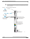
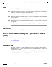
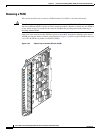
A physical layer interface module (PLIM) is paired with an MSC through the midplane of the chassis.
A PLIM provides the ability to choose several interfaces.
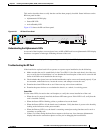
Figure 4-32 shows a typical PLIM (in this case
a 16 x OC-48c/STM-16c packet-over-SONET [POS]).