


3-7
Cisco CRS-1 Carrier Routing System 8-Slot Line Card Chassis Installation Guide
OL-6256-08
Chapter 3 Installing and Removing Air Circulation Components
How to Install or Remove Air Circulation Components
Caution To prevent damage to the chassis connector, do not use excessive force when inserting a fan
tray into its bay.
Step 8 Firmly push on the fan tray to seat the fan tray connector in the chassis connector.
Note All electrical and control line connections are made automatically when the connectors mate.
Step 9 Rotate the fan tray handle to the closed (flush) position.
Step 10 Replace the fan tray bay door and tighten the two captive screws on the fan tray bay door.
What to Do Next
After performing this task, replace the front cover plates.
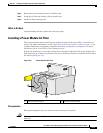
Removing an Upper Fan Tray
This section describes how to remove a fan tray from the upper fan tray slot of the Cisco CRS-1 8-slot
line card chassis. For information on the chassis airflow and circulation, see the
“About Line Card
Chassis Airflow” section on page 3-1. For complete information on regulatory compliance and safety,
see Regulatory Compliance and Safety Information for the Cisco CRS-1 Carrier Routing System.
A Cisco CRS-1 8-slot line card chassis fan tray operates in either the upper or lower fan tray slot. Each
fan tray is installed into the rear (MSC) side of the chassis (see
Figure 3-5).
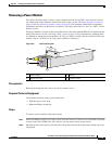
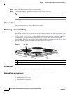
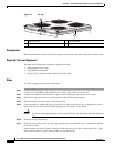
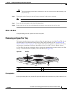
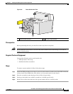
Figure 3-5 Fan Tray
Prerequisites
Before performing this task, you must first open the chassis doors and remove any front cosmetic covers.
1 Captive screws 3 Fan tray handle
2 Fan tray rail
122289
3
2
1