


5-7
Cisco CRS-1 Carrier Routing System 8-Slot Line Card Chassis Installation Guide
OL-6256-08
Chapter 5 Installing and Removing Exterior Components
Installing or Removing the Front Side Exterior Components
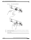
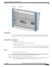
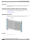
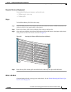
Figure 5-4 Inlet Grille
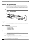
Prerequisites
No prerequisites exist for this task.
Required Tools and Equipment
You need the following tools to perform this task:
• ESD-preventive wrist strap
Steps
To remove the inlet grille, follow these steps:
Step 1 Attach the ESD-preventive wrist strap to your wrist and connect its leash to one of the ESD connection
sockets on the front (PLIM) side of the chassis or a bare metal surface on the chassis.
Step 2 While facing the front (PLIM) side of the chassis, firmly grasp the top outside edges of the inlet grille.
Step 3 Pull the top of the grille firmly away from the chassis; it loosens from the connecting ball studs.
Step 4 Slide the hooks at the bottom of the grille free of the cutouts at the bottom of the chassis casing.
Step 5 Carefully set the inlet grille aside.
210878
OT
I/LIM
(
A
C
O
N
L
Y
)
CB/TRIP
IN/FAIL
FLT
PWR/OK
O
T
I/LIM
(A
C
O
N
L
Y
)
CB/TRIP
IN
/FAIL
FLT
PW
R
/O
K