


3-2
Cisco CRS-1 Carrier Routing System 8-Slot Line Card Chassis Installation Guide
OL-6256-08
Chapter 3 Installing and Removing Air Circulation Components
How to Install or Remove Air Circulation Components
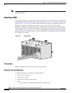
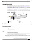
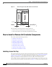
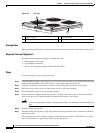
Figure 3-1 Airflow Through the Cisco CRS-1 8-Slot Line Card Chassis
The Cisco CRS-1 8-slot line card chassis airflow volumes are:
• Chassis airflow: Up to 900 cubic feet (25,485 liters) per minute
• Power system airflow: Up to 240 cubic feet (6,800 liters) per minute
How to Install or Remove Air Circulation Components
This section contains the following procedures:
• Installing a Lower Fan Tray
• Removing a Lower Fan Tray
• Installing an Upper Fan Tray
• Removing an Upper Fan Tray
• Installing the Chassis Air Filter
• Removing the Chassis Air Filter
• Installing a Power Module Air Filter
• Removing a Power Module Air Filter
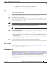
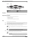
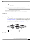
Installing a Lower Fan Tray
This section describes how to install a fan tray in the lower fan tray slot of the Cisco CRS-1 8-slot line
card chassis. For information on the chassis airflow and circulation, see the
“About Line Card Chassis
Airflow” section on page 3-1. For complete information on regulatory compliance and safety, see
Regulatory Compliance and Safety Information for the Cisco CRS-1 Carrier Routing System.
A Cisco CRS-1 8-slot line card chassis fan tray operates in either the upper or lower fan tray slot. Each
fan tray installs into the rear (MSC) side of the chassis (see
Figure 3-2). Each fan tray contains four fans.
122784
Fan
Air enters
PLIM side
Power system
Fan
Air exits MSC and
fabric card side
Front Rear
Air filter