


4-41
Cisco CRS-1 Carrier Routing System 8-Slot Line Card Chassis Installation Guide
OL-6256-08
Chapter 4 Installing and Removing MSCs, PLIMs, and Associated Components
How to Install or Remove an RP Card or DRP PLIM
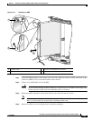
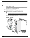
Step 9 Pivot both card ejector levers so that the openings on the card ejector cams at the top and bottom of the
card pass over the tabs on each side of the card cage slot.
Caution Verify that the openings on the card ejector cams pass over the tabs; otherwise, one or both
ejector levers may bind when you attempt to close the ejector levers, thereby damaging or
breaking one or both ejector levers.
Step 10 Continue sliding the card into the card cage slot until the openings on the card ejector cams engage the
tabs on each side of the card cage slot.
Note An RP or DRP card has guide pins that make initial contact with the backplane connector as you
slide the card into its slot. After the guide pins make contact, continue pushing on the card carrier
until the card ejector levers begin pivoting forward, toward the handle in the card carrier.
Step 11 To seat the card in the backplane connector, grasp both card ejector levers and pivot them inward toward
the handle in the card carrier until they are flush against the front edge of the card carrier.
Step 12 Partially tighten the two captive screws on the front panel of the card (either by hand or with the
screwdriver) to make sure that they are both engaged.
Step 13 Use the screwdriver to turn the two captive screws on the front panel of the card clockwise to seat the
card firmly in the slot.
Step 14 Reattach any cables you removed in Step 3.
What to Do Next
After performing this task:
• Place the impedance carrier in an antistatic bag for storage and future use.
• Replace any front cover cosmetic plates and verify that the card has been installed properly (see the
“Verifying the Installation of an RP or DRP Card” section on page 4-42).
• If you are performing the initial installation of the system, install the PLIMs (see the “Installing a
PLIM” section on page 4-46).
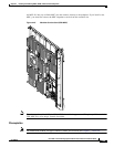
Removing an RP or DRP Card
This section describes how to remove a route processor (RP) or distributed route processor (DRP) card
from the chassis. For more detailed information on the route processor card, see Cisco CRS-1 Series
Carrier Routing System 8-Slot Line Card Chassis System Description.
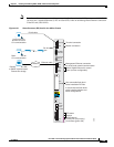
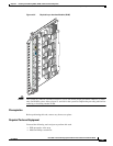
Every Cisco CRS-1 8-slot line card chassis contains two route processor cards in dedicated slots on the
front (PLIM) side of the chassis (see
Figure 4-28 on page 4-39).
Note For enhanced immunity to external electromagnetic disturbance levels of 10V per meter and 10 V RMS,
you must use a shielded Ethernet (CAT5 or better STP) cable on the Management Ethernet connection
of the RP card (CRS-8-RP).