


2-4
Cisco CRS-1 Carrier Routing System 8-Slot Line Card Chassis Installation Guide
OL-6256-08
Chapter 2 Installing and Removing Power Components
Information About Installing and Removing the Power Components
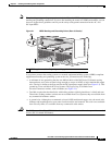
DC Power Systems
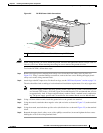
A DC-powered Cisco CRS-1 8-slot line card chassis contains two DC-input power distribution units
(PDUs) and two DC power entry modules (PEMs). Each DC PDU is connected to three pairs of DC
power feeds and powers a single 7500-watt DC PEM that is field replaceable. Input DC power enters the
PDU and is passed to the PEM, which provides power to the components in the chassis. Each PEM has
its own circuit breaker.
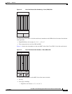
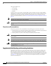
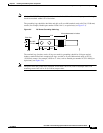
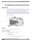
The DC PDU is shipped with a plastic safety cover over the input terminal block (see Figure 2-2). This
safety cover is in two parts, each part held on to the PDU with a Phillips screw. We recommend removing
the safety cover only when wiring and unwiring the chassis. The safety cover is slotted in such a way
that the wires can only come out on the bottom portion of the cover.
Figure 2-2 DC PDU with Plastic Safety Cover
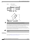
Each PDU requires three DC inputs of –48/–60 VDC (nominal), 60-amp service. The PDU accepts input
DC power in the range –40.5 to –75 VDC, and has three sets of double-stud terminals (-48/-60VDC Lines
and -48/-60VDC Returns) for connecting to the VDC inputs.
Each DC PDU should be connected to a different central office DC power source:
• One PDU should be connected to three –48/–60 VDC “A” buses.
• The other PDU should be connected to three –48/–60 VDC “B” buses.
If DC power to a PDU fails, the other PDU provides enough power for the chassis. This 2N power
redundancy enables the routing system to operate in spite of single power failure.
For DC power cables, we recommend that you use commensurately rated, high-strand-count copper wire
cable, based on local electrical codes. These wires are not available from Cisco Systems; they are
available from any commercial vendor. DC power cables must be terminated by cable lugs at the power
shelf end.
1 Each set of cables (RTN and –48V/–60V) is a single VDC input.
129533
1