


2-3
Cisco CRS-1 Carrier Routing System 8-Slot Line Card Chassis Installation Guide
OL-6256-08
Chapter 2 Installing and Removing Power Components
Information About Installing and Removing the Power Components
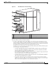
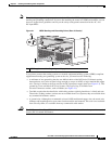
Note These bonding and grounding receptacles satisfy the Telcordia NEBS requirements for supplemental
bonding and grounding connections. If you are not installing the router in a NEBS environment, you can
choose to bypass these guidelines and rely on the safety earth ground connection for the AC- and
DC-input PDUs.
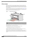
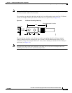
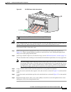
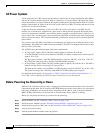
Figure 2-1 NEBS Bonding and Grounding Points (Rear of Chassis)
If you plan to connect the routing system to a network equipment building system (NEBS)-compliant
supplemental bonding and grounding system at the site, you must have the following:
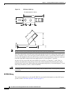
• A minimum of one ground lug that has two M6 bolt holes with 0.625-inch (15.86-mm) spacing
between them, and a wire receptacle large enough to accept a 6-AWG or larger multistrand copper
wire. The lug is similar to the type used for the DC-input power supply leads (see
Figure 2-3). This
ground lug is not available from Cisco Systems. This type of lug is available from
electrical-connector vendors, such as Panduit (see
Figure 2-3).
• Two M6 or equivalent hex-head bolts with locking washers (nickel-plated brass is ideal) and nuts.
These bolts, locking washers, and nuts are not available from Cisco Systems; they are available from
any commercial hardware vendor.
• A ground wire. Although we recommend at least 6-AWG multistrand copper wire, the actual wire
diameter and length depend on your router location and site environment. This wire is not available
from Cisco Systems; it is available from any commercial cable vendor.
Caution The DC Return of the Cisco CRS-1 8-slot chassis should remain isolated from the system frame and
chassis (DC-I: Isolated DC Return).
1 NEBS supplemental bonding and grounding points
122792
1