


CHAPTER
2-1
Cisco CRS-1 Carrier Routing System 8-Slot Line Card Chassis Installation Guide
OL-6256-08
2
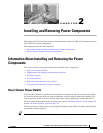
Installing and Removing Power Components
This chapter provides instructions on how to install and remove the Cisco CRS-1 Carrier Routing System
Line Card Chassis power components.
This chapter presents the following topics:
• Information About Installing and Removing the Power Components
• How to Install or Remove the Power Components
Information About Installing and Removing the Power
Components
This section contains some general information about the power components.
• Basic Chassis Power Details
• Supplemental Unit Bonding and Grounding Guidelines
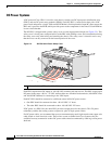
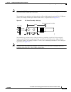
• DC Power Systems
• AC Power Systems
• Before Powering the Chassis Up or Down
• Converting from One Power System to Another
Basic Chassis Power Details
The Cisco CRS-1 8-slot line card chassis can be either DC or AC powered. The chassis power system (DC or
AC) provides the necessary power for chassis components. A chassis with AC input power requires 8,750
watts to power the chassis. A chassis with DC input power requires 8,000 watts to power the chassis.
For more detailed information on the two power types, see the “DC Power Systems” section on page 2-4
and the “AC Power Systems” section on page 2-8.
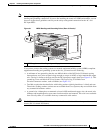
The line card chassis requires that at least the power distribution units (PDUs) and their power modules
be installed to operate properly.
Tip Be sure to install the PDUs before installing the power modules.