


Index
IN-3
Cisco CRS-1 Carrier Routing System 8-Slot Line Card Chassis Installation Guide
OL-6256-08
MSC impedance carrier 4-9, 4-17, 4-19
NEBS bonding and grounding 2-3
operating ejector levers 4-3
PLIM 4-47, 4-50
PLIM front panel 4-53
PLIM impedance carrier 4-8
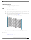
rear view of line card chassis 1-3
removing a pillow block 4-23
removing bale-claps SFP 4-57
removing MSC 4-36
removing PLIM 4-52
removing switch fabric card 4-28
RP card front panel 4-43
RP card PCMCIA slot door 4-44, 4-45
RP impedance carrier 4-7
slot numbers (front) 1-5, 4-4
slot numbers (rear) 1-5, 4-4
switch fabric card 4-24, 4-27
switch fabric card (front view) 4-29
switch fabric slot cover 4-6, 4-14, 4-15
filter, air 1-6, 3-1
G
grille, inlet (figure) 5-5, 5-7, 5-8, 5-9
grounding
(figure) 2-3
guidelines 2-2
H
hard drives 4-12
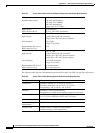
heat dissipation specification A-2
humidity guidelines A-2
I
impedance carrier
about 4-6
installing 4-16
MSC (figure) 4-9, 4-17, 4-19
PLIM (figure) 4-8
removing 4-18
RP (figure) 4-7
inlet grille
(figure) 5-5, 5-7, 5-8, 5-9
installing 5-4
removing 5-6
installation steps
lower fan try 3-3
upper fan try 3-6
installing
air circulation components 3-1, 3-2
air filter 3-8
bale-clasp SFP 4-54
cable management brackets 5-3
DRP card 4-38
exterior components 5-1
inlet grille 5-4
lower fan try 3-2
MSC 4-30
MSCs, PLIMs, and components 4-1
PCMCIA card 4-44
PDU 2-10, 2-11
PLIM 4-46
power components 2-1, 2-9
power module 2-13
power module, steps 2-14
power module air filter 3-11
RP card 4-38
SFP modules 4-53
switch fabric card 4-23
upper fan tray 3-5