


5-9
Cisco CRS-1 Carrier Routing System 8-Slot Line Card Chassis Installation Guide
OL-6256-08
Chapter 5 Installing and Removing Exterior Components
Installing or Removing the Rear Side Exterior Components
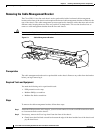
Required Tools and Equipment
You need the following tool and part to perform this task:
• ESD-preventive wrist strap
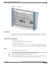
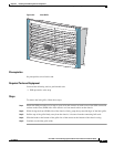
• Exhaust grille
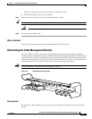
Steps
To install the exhaust grille, follow these steps:
Step 1 Attach the ESD-preventive wrist strap to your wrist and connect its leash to an ESD connection socket
on the rear side or a bare metal surface on the chassis.
Step 2 Remove the exhaust grille from its packaging, then set the packaging aside.
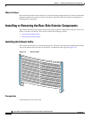
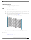
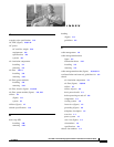
Step 3 Align and insert the hooks at the bottom of the exhaust grille into the cutouts at the bottom of the chassis
casing on the rear side of the chassis, as shown in
Figure 5-6.
Figure 5-6 Inserting the Exhaust Grille Hooks Into the Chassis
Step 4 Rotate the top of the exhaust grille toward the chassis, and snap it into place on the ball studs.
What to Do Next
After performing this task, you may power on the chassis. See the “Before Powering the Chassis Up or
Down” section on page 2-8.
158083