


2-15
Cisco CRS-1 Carrier Routing System 8-Slot Line Card Chassis Installation Guide
OL-6256-08
Chapter 2 Installing and Removing Power Components
How to Install or Remove the Power Components
Removing a Power Module
This section describes how to remove a power module from the Cisco CRS-1 8-slot line card chassis.
For information on the difference between the power types, see the
“DC Power Systems” section on
page 2-4 and the “AC Power Systems” section on page 2-8. For complete information on regulatory
compliance and safety, see Regulatory Compliance and Safety Information for the Cisco CRS-1 Carrier
Routing System.
The power module is located on the front of the chassis, and mates with the PDU that is installed on the
back of the chassis (see the
“Installing a PDU” section on page 2-10 for information). Although there
are differences among the power modules (AC Wye, AC Delta, and DC), they are installed in the same
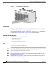
manner. (
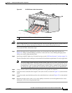
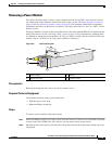
Figure 2-9 shows an AC Wye power rectifier for reference.)
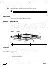
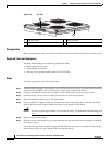
Figure 2-9 AC Power Rectifier
Prerequisites
Before performing this task, remove any front cosmetic covers.
Required Tools and Equipment
You need the following tools to perform this task:
• ESD-preventive wrist strap
• Medium Phillips screwdriver
Steps
To remove a power module, follow these steps:
Step 1 Attach the ESD-preventive wrist strap to your wrist and connect its leash to one of the ESD connection
sockets on the front (PLIM) side of the chassis or a bare metal surface on the chassis.
Step 2 On the front side of the chassis, pull the power tab on the bottom front of the power module out to the
off position.
1 Power switch 3 Handle
2 Module air filter 4 Captive screws
P
O
W
E
R
O
K
F
LT
A
C
FA
IL
C
B
T
M
P
LLM
OT
122286
3
1
2
4