


3-6
Cisco CRS-1 Carrier Routing System 8-Slot Line Card Chassis Installation Guide
OL-6256-08
Chapter 3 Installing and Removing Air Circulation Components
How to Install or Remove Air Circulation Components
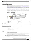
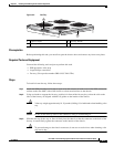
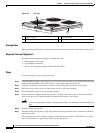
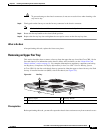
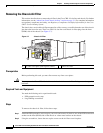
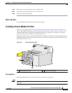
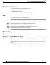
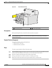
Figure 3-4 Fan Tray
Prerequisites
Before performing this task, you must first open the chassis doors and remove any front cosmetic covers.
Required Tools and Equipment
You need the following tools and parts to perform this task:
• ESD-preventive wrist strap
• Large Phillips screwdriver
• Fan tray (Cisco product number CRS-8-LCC-FAN-TR=)
Steps
To install an upper fan tray, follow these steps:
Step 1 Attach the ESD-preventive wrist strap to your wrist and connect its leash to one of the ESD connection
sockets on the rear (MSC) side of the chassis or a bare metal surface on the chassis.
Step 2 Using the screwdriver, unscrew the two captive screws holding the fan tray bay door in place.
Step 3 Lift the door up; you may need a second person to hold it in the open position.
Step 4 Rotate the handle on the fan tray to the open position.
Step 5 Using two hands to support the fan tray, position it in front of the fan tray bay so that the rails on the
sides of the fan tray are aligned with the rail guides on the interior of the chassis.
Caution A fan tray weighs approximately 19.15 pounds (8.69 kg). Use both hands when handling a fan
tray.
Step 6 Slide the fan tray into the bay.
Step 7 Slide the fan tray into the fan tray bay. Stop when the fan tray meets the chassis connector in the back
of the fan tray bay.
Notice that the tray (and rail guides) drop just inside the fan tray bay door, so that the fan tray “drops”
into its final position as it gets almost all the way into the chassis.
1 Captive screws 3 Fan tray handle
2 Fan tray rail
122289
3
2
1