


4-43
Cisco CRS-1 Carrier Routing System 8-Slot Line Card Chassis Installation Guide
OL-6256-08
Chapter 4 Installing and Removing MSCs, PLIMs, and Associated Components
How to Install or Remove an RP Card or DRP PLIM
This section describes how to verify that the card has been properly installed. Status indicators on the
RP front panel include:
• Alphanumeric LED display
• Status OK LED
• Active/Standby LED
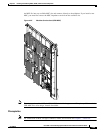
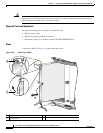
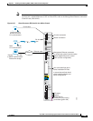
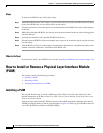
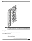
Figure 4-29 shows the RP card front panel.
Figure 4-29 RP Card Front Panel
Understanding the Alphanumeric LEDs
At one end of the faceplate, near an ejector lever, an RP or DRP card has an alphanumeric LED display
that shows a sequence of messages indicating the state of the card.
Note It is normal for some displayed messages to appear too briefly in the LED display to be read.
Troubleshooting the RP Card
If the installed or replaced card fails to operate or to power up on installation, do the following:
1. Make sure that the card is seated firmly in the Cisco CRS-1 8-slot line card chassis slot. One easy
way to verify physical installation is to see whether the front faceplate of the card is even with the
fronts of the other cards installed in the card cage.
2. Check whether the ejector levers are latched and that the captive screws are fastened properly. If you
are uncertain, unlatch the levers, loosen the screws, and attempt to reseat the card.
3. Examine the alarm LEDs on the to see if there are any active alarm conditions.
4. Examine the power shelves to see whether the chassis, as a whole, is receiving power.
Status LEDs
Use the status LEDs, located on the card faceplate, to verify the correct installation of the card:
• When the card is properly installed, the Status LED turns green. If this LED is off, verify that the
card is installed correctly.
• When the Status LED is blinking yellow, a problem exists on the board.
• When the Status LED is off, the board state is unknown. Verify that there is power to the board by
looking at the indicators on the power module.
• When the Primary LED is on, the board is executing control processing functions and is not in a
secondary or standby role.
• If there is a failure during the board boot sequence, the four-row, four-character alphanumeric
display indicates the current boot phase to assist you in debugging the board failure.
CONSOLE
AUX
HDD
MGMNT ETH
CNTL ETH1
CNTL ETH0
PC CARD
CRS-16-RP
STATUS
PRIMARY
101779