


3-11
Cisco CRS-1 Carrier Routing System 8-Slot Line Card Chassis Installation Guide
OL-6256-08
Chapter 3 Installing and Removing Air Circulation Components
How to Install or Remove Air Circulation Components
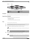
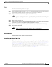
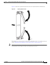
Step 3 Remove the cover faceplate and set it carefully aside.
Step 4 Grasp the air filter and carefully slide it from the slot.
Step 5 Set the air filter carefully aside.
What to Do Next
After performing this task, replace the front cover plates.
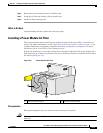
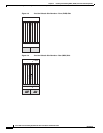
Installing a Power Module Air Filter
This section describes how to install a power module air filter for the Cisco CRS-1 8-slot line card
chassis. For further information, see the
“About Line Card Chassis Airflow” section on page 3-1. For
complete information on regulatory compliance and safety, see Regulatory Compliance and Safety
Information for the Cisco CRS-1 Carrier Routing System.
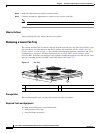
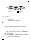
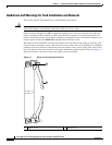
Each power module has a serviceable air filter that is attached to the front of the power module and is
held in place by an air filter clip-on holder. The power module air filter faces outward from the front of
the chassis (see
Figure 3-8).
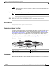
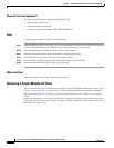
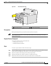
Figure 3-8 Power Module Air Filter
Prerequisites
Before performing this task, you must first remove any front cover plates.
Caution Never operate the Cisco CRS-1 8-slot line card chassis without an air filter. Doing so can damage the
hardware.
1 Power module air filter 2 Air filter clip-on holder
P
O
W
E
R
O
K
FL
T
A
C
F
A
IL
C
B
T
M
P
L
LM
O
T
122788
2
1