


2-7
Cisco CRS-1 Carrier Routing System 8-Slot Line Card Chassis Installation Guide
OL-6256-08
Chapter 2 Installing and Removing Power Components
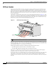
Information About Installing and Removing the Power Components
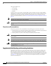
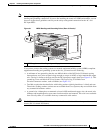
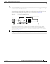
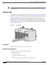
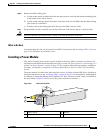
Figure 2-5 DC PDU Power Cable Connections
Caution When wiring the PDU, be sure to attach the ground wire first and tighten the nuts to a torque value of
30 in-lb (3.39 N-m). When removing the wiring, be sure to remove the ground wire last.
To wire the DC PDU, follow these steps:
Step 1 Remove the upper plastic terminal block safety cover (leave the lower safety cover in place; see
Figure 2-5). Using a standard Phillips screwdriver, remove the four screws holding the upper plastic
safety cover to the wiring terminal block.
Step 2 Attach lugs to the DC-input wires. For details on lugs, see the “DC Power Systems” section on page 2-4.
The wire should be sized according to local and national installation requirements. Use only copper wire.
Note The power supply terminal block lug opening width is 0.62 inch (15.8 mm). The terminal posts
are centered 0.625 inches (15.88 mm) apart and are M6-threaded. We recommend that you use
an appropriately sized 45-degree angled industry standard 2-hole, standard barrel compression
lug. The power supply ground studs, located below the terminal block, are also M6-threaded.
Step 3 Using a 10-mm socket wrench, attach the ground wire to the ground wire terminal.
Step 4 Using the wrench, attach the three negative wires (the red wires as shown in Figure 2-5) to the terminal
block.
Step 5 Using the wrench, attach the three positive wires (the black wires as shown in Figure 2-5) to the terminal
block.
Step 6 Reattach the upper plastic safety cover: with a phillips screwdriver, insert and tighten the four screws
holding the cover to the wiring terminal block.
1 Each set of cables (RTN and –48V/–60V) is a single VDC input.
129533
1