


2-13
Cisco CRS-1 Carrier Routing System 8-Slot Line Card Chassis Installation Guide
OL-6256-08
Chapter 2 Installing and Removing Power Components
How to Install or Remove the Power Components
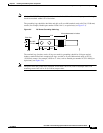
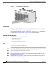
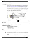
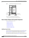
Step 6 Remove the PDU holding plate.
a. Use the socket wrench to unbolt the four 8-mm bolts (two for each side) that attach the holding plate
to the interior of the side of chassis.
b. Use the socket wrench to unbolt the eight 10-mm bolts (four for each PDU) that attach the holding
plate to the top of the PDUs.
c. Carefully remove the holding plate from the top of the PDUs and set it aside.
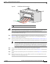
Step 7 Grasp the PDU and lift it carefully over the lip at the back of the chassis and set it carefully aside.
Caution Do not lift the PDU by the power cord—doing so can damage the PDU or the cord.
What to Do Next
After performing this task, you may install a new PDU, if needed (see the “Installing a PDU” section on
page 2-10), and replace any cosmetic covers.
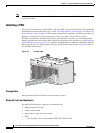
Installing a Power Module
This section describes how to install a power module in the Cisco CRS-1 8-slot line card chassis. For
information on the difference between the power types, see the
“DC Power Systems” section on page 2-4
and the “AC Power Systems” section on page 2-8. For complete information on regulatory compliance
and safety, see Regulatory Compliance and Safety Information for the Cisco CRS-1 Carrier Routing
System.
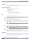
The power module is installed into the front of the chassis, and mates with the PDU that is installed on
the back of the chassis (see the
“Installing a PDU” section on page 2-10 for information). Although there
are differences among the different power modules (AC Wye, AC Delta, and DC), they are installed in
the same manner. (
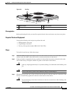
Figure 2-8 shows an AC Wye power rectifier for reference.)
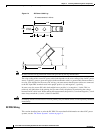
Figure 2-8 AC Power Rectifier
1 Power switch 3 Handle
2 Module air filter 4 Captive screws
P
O
W
E
R
O
K
F
L
T
A
C
F
A
IL
C
B
T
M
P
LL
M
O
T
122286
3
1
2
4