


2-2
Cisco CRS-1 Carrier Routing System 8-Slot Line Card Chassis Installation Guide
OL-6256-08
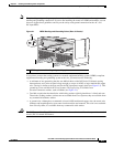
Chapter 2 Installing and Removing Power Components
Information About Installing and Removing the Power Components
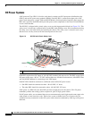
Three types of PDUs exist:
• AC Wye PDU
• AC Delta PDU
• DC PDU
AC PDUs connect to AC rectifiers, while DC PDUs connect to the DC power entry modules (PEMs).
Although there are differences among the different PDU types (AC Wye, AC Delta, and DC), they are
installed in the same manner. Similarly, the different power modules are also installed in the same
manner. For detailed information, see the
“How to Install or Remove the Power Components” section on
page 2-9.
Note The PDUs arrive with the power cables preattached.
Caution Use only one type of PDU—AC Wye, AC Delta, or DC—and its mating power module in a chassis at
one time.
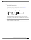
Precautions and Recommendations
Follow these precautions and recommendations when planning power connections to the router:
• Check the power at your site before installation and periodically after installation to ensure that you
are receiving clean power. Install a power conditioner, if necessary.
• Properly ground your system to avoid damage from lightning and power surges.
Caution To ensure electromagnetic compatibility, a Cisco router must be operated with all its power modules
always installed.
Note You must have the chassis horizontal mounting rails installed in the rack to ensure EMI compliance.
Warning
This unit might have more than one power supply connection. All connections must be removed to
de-energize the unit.
Statement 1028
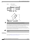
Supplemental Unit Bonding and Grounding Guidelines
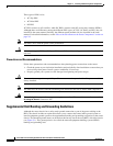
Although the router chassis has a safety earth ground connection as part of the power cabling to the
PDUs, the chassis includes an option that allows you to connect the central office ground system or
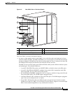
interior equipment ground system to the supplemental bonding and grounding receptacles on the router
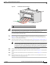
chassis. Two threaded ground inserts are located on the fan tray door at the rear (MSC) side of the chassis
(see
Figure 2-1). This ground point is also called the network equipment building system (NEBS)
bonding and grounding stud.