


PERC 3/SC Hardware Installation 105
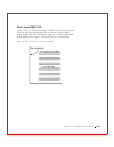
Step 3—Set Jumpers
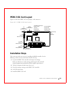
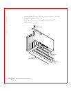
Make sure the jumper settings on the PERC 3/SC card are correct. The
jumpers and connectors are shown in Table 8-1.
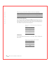
J1 Termination Enable
J1 is a three-pin header that specifies hardware or software control of SCSI
termination. The default is OPEN. The settings are shown in Table 8-2.
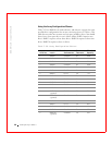
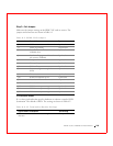
Table 8-1. PERC 3/SC Jumpers
Connector Description Type
J1 SCSI bus termination enable control 3-pin header
J2 CPLD programming 10-pin header
J3 Non-volatile random access memory
(NVRAM) clear
2-pin header
J4 Serial erasable programmable read-
only memory (EPROM)
2-pin header
J5 Serial port 3-pin header
J6 Write pending 2-pin header
J7 BIOS enable 2-pin header
J8 User activity light-emitting diode
(LED)
4-pin connector
J9 I2C connector 4-pin header
J10 SCSI bus termination power 2-pin header
J11 Internal straddle-mount connector 68-pin connector
J13 External SCSI connector 68-pin connector
J15 RUBI slot interrupt steering 3-pin header
J16 RUBI slot interrupt steering 3-pin header
J17 RUBI slot interrupt steering 3-pin header
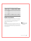
Table 8-2. J1 Termination Enable Settings
Type of SCSI Termination J10 Setting
Software control of SCSI termination using drive
detection.
Short pins 1-2