


124 PERC 3/DC or PERC 3/DCL Hardware Installation
www.dell.com | support.dell.com
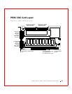
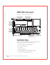
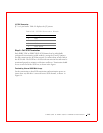
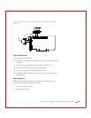
J14 SCSI Activity LED
J14 is a four-pin connector for an LED mounted on the computer enclosure.
Table 9-7 displays the J14 pinout.
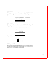
J16 and J18 TERMPWR Enable
J16, and J18 are 2-pin connectors that enable termination power to the
SCSI bus for each SCSI channel. The default is pins 1 and 2 jumpered.
Table 9-8 displays the settings for J16 and J18.
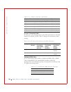
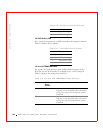
Table 9-6. J13 Dirty Cache LED Pinout
Pin Description
1 Signal pulled high
2 Dirty cache signal
Table 9-7. J14 SCSI Activity Pinout
Pin Description
1VCC
2 SCSI activity signal
3 SCSI activity signal
4VCC
Table 9-8. J16 and J18 TERMPWR Enable Settings
Jumper Termination
Power
Channel
Settings
J16 0 Short pins 1-2 to have the PCI bus on the host
computer provide TermPWR. This is the default
setting. Leave open to let the SCSI bus provide
Te rm PW R.
J18 1 Short pins 1-2 to have the PCI bus on the host
computer provide TermPWR. This is the default
setting. Leave open to let the SCSI bus provide
Te rm PW R.