


138 PERC 3/QC Hardware Installation
www.dell.com | support.dell.com
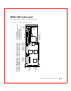
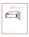
J2, J3, J5, and J7 Termination Enable
J2, J3, J5, and J7 are 3-pin connectors that set the SCSI termination for each
SCSI channel. The Dell default is termination always enabled (OPEN.)
Table 10-2 displays the pinout.
J9, J10, J11, and J12 TERMPWR Enable
J9, J10, J11, and J12 are 2-pin connectors that enable TERMPWR to the
SCSI bus for each SCSI channel. The default is pins 1 and 2 shorted. Table
10-3 displays the pinout.
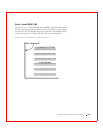
Table 10-2. J2, J3, J5 and J7 Termination Enable Pinout
Jumper SCSI
Channel
SCSI
Termination
Controlled by
Software
SCSI
Termination
Always
Disabled
SCSI
Termination
Always Enabled
J2 0 Short pins 1-2 Short pins 2-3 OPEN (default)
J3 1 Short pins 1-2 Short pins 2-3 OPEN (default)
J5 2 Short pins 1-2 Short pins 2-3 OPEN (default)
J7 3 Short pins 1-2 Short pins 2-3 OPEN (default)
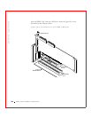
Table 10-3. J9, J10, J11 and J12 TERMPWR Enable Pinout
Jumper Term.
Power
Channel
Settings
J9 0 Short pins 1-2 to have the host PCI bus provide
TermPWR. This is the factory setting. Leave open to let
the SCSI bus provide TermPWR.
J10 1 Short pins 1-2 to have the host PCI bus provide
TermPWR. This is the factory setting. Leave open to let
the SCSI bus provide TermPWR.
J11 2 Short pins 1-2 to have the host PCI bus provide
TermPWR. This is the factory setting. Leave open to let
the SCSI bus provide TermPWR.
J12 3 Short pins 1-2 to have the host PCI bus provide
TermPWR. This is the factory setting. Leave open to let
the SCSI bus provide TermPWR.