


PERC 3/DC or PERC 3/DCL Hardware Installation 125
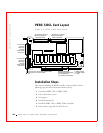
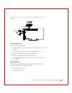
J17 I2C Connector
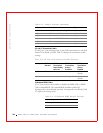
J17 is a 4-pin header. Table 9-9 displays the J17 pinout.
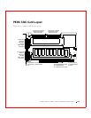
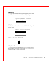
Step 4—Set SCSI Termination
Each PERC 3/DC or PERC 3/DCL SCSI channel can be individually
configured for termination enable mode by setting the J2 and J3 jumpers.
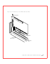
You must terminate the SCSI bus properly. Set termination at both ends of
the SCSI cable. The SCSI bus is an electrical transmission line and must be
terminated properly to minimize reflections and losses. Termination should
be set at each end of the SCSI bus, as shown in the figures.
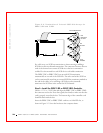
Terminating Internal SCSI Disk Arrays
Set the termination so that SCSI termination and termination power are
intact when any disk drive is removed from a SCSI channel, as shown in
Figure 9-4.
Table 9-9. J17 I2C Connector Pinout
Pin Description
1Data
2GND
3Clock
4 Power (fused)