


PERC 3/QC Hardware Installation 139
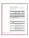
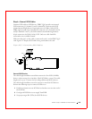
J14 Serial Port
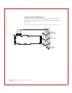
J14 attaches to a serial cable. Figure 10-2 and Table 10-4 show the pinout for
J14.
Figure 10-2. J14 Serial Port Diagram
J17 Dirty Cache LED
J17 is a two-pin connector for an LED mounted on the computer enclosure.
The LED indicates when the data in the cache has yet to be written to the
storage devices. Table 10-5 displays the pinout for J17.
J19 Onboard BIOS Enable
J19 is a 2-pin connector which enables or disables PERC 3/QC onboard
BIOS. The onboard BIOS should be enabled (J19 unjumpered) for normal
board position. Unjumpered is the default. Table 10-6 displays the J19
settings.
Table 10-4. J14 Serial Port Pinout
Pin Description Pin Description
1 Carrier detect 2 Data set ready
3 Receive data 4 Request to send
5 Transmit data 6 Clear to send
7 Data terminal ready 8 Ring indicator
9Ground 10CUT
Table 10-5. J17 Dirty Cache LED Pinout
Pin Description
1 Signal pulled high
2 Dirty cache signal
2 468
13579