


140 PERC 3/QC Hardware Installation
www.dell.com | support.dell.com
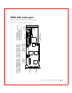
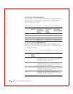
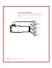
J23 External Battery
J23 is a 5-pin connector that attaches to the optional battery pack. Table 10-
7 displays the J23 pinout.
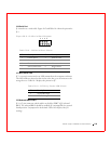
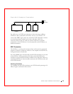
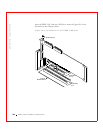
Step 4—Set SCSI Termination
You must terminate the SCSI bus properly. Set termination at both ends of
the SCSI cable. The SCSI bus is an electrical transmission line and must be
terminated properly to minimize reflections and losses. Termination should
be set at each end of the SCSI cable(s), as shown below. Termination is
always enabled, regardless of the configuration. However, you can override
this setting by setting another state. The Dell default is termination by
jumper. Figure 10-3 displays an example of termination.
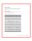
Table 10-6. J19 Onboard BIOS Enable Settings
J19 Setting Onboard BIOS Status
Unjumpered Enabled
Jumpered Disabled
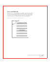
Table 10-7. J23 External Battery Pinout
Pin Description
1 +BATT Terminal (red wire)
2 Thermistor (white wire)
3 -BATT Terminal (black wire)
4BATDQ (no wire)
5Ground (no wire)