


PERC 3/QC Hardware Installation 137
Step 2—Power Down
Turn off the computer and remove the cover. Make sure the computer is
turned off and disconnected from any networks before installing the
controller.
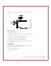
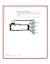
Step 3—Set Jumpers
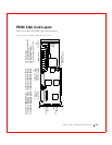
Make sure the jumper settings on the PERC 3/QC card are correct. Table
10-1 displays the jumpers and connectors.
Table 10-1. PERC 3/QC Jumper Settings
Connector Description Type
J1 Channel 1 internal Wide SCSI 68-pin connector
J2 Channel 0 termination enable 3-pin header
J3 Channel 1 termination enable 3-pin header
J4 Channel 0 internal Wide SCSI 68-pin connector
J5 Channel 2 termination enable 3-pin header
J6 SCSI activity light emitting diode
(LED)
4-pin header
J7 Channel 3 termination enable 3-pin header
J9 Channel 0 TERMPWR enable 2-pin header
J10 Channel 1 TERMPWR enable 2-pin header
J11 Channel 2 TERMPWR enable 2-pin header
J12 Channel 3 TERMPWR enable 2-pin header
J13 Channel 0/1 external Wide SCSI Dual 68-pin connector
J14 Serial port connector 9-pin connector
J17 Dirty cache LED 2-pin connector
J18 Serial EEPROM port 2-pin header
J19 Onboard BIOS enable 2-pin header
J22 Channel 2/3 external Wide SCSI Dual 68-pin connector
J23 External battery connector 5-pin connector