


122 PERC 3/DC or PERC 3/DCL Hardware Installation
www.dell.com | support.dell.com
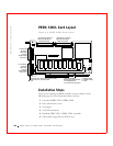
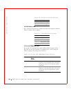
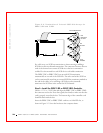
J2, and J3 Termination Enable
J2, and J3 are 3-pin connectors that set the SCSI termination for each SCSI
channel. The default is OPEN. Table 9-2 displays the termination enable
settings.
J9 Onboard BIOS Enable
J9 is a 2-pin connector that enables or disables the PERC 3/DC or PERC
3/DCL onboard BIOS. The onboard BIOS should be enabled (J9
unjumpered) for normal board operation. Unjumpered is the default. Table
9-3 displays the settings for J9.
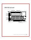
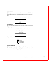
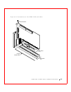
J13 Dirty cache (Write Pending) LED 2-pin header
J14 SCSI activity LED 4-pin header
J15 Channel 1 external Wide SCSI 68-pin connector
J16 Channel 0 TERMPWR enable 2-pin header
J17 I2C connector 4-pin header
J18 Channel 1 TERMPWR enable 2-pin header
Table 9-2. J2 and J3 Termination Enable Settings
Jumper SCSI
Channel
SCSI
Termination
Controlled by
Software
SCSI
Termination
Always
Disabled
SCSI
Termination
Always
Enabled
J2 0 Short pins 1-2 Short pins 2-3 OPEN
(default)
J3 1 Short pins 1-2 Short pins 2-3 OPEN
(default)
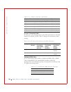
Table 9-3. J9 Onboard BIOS Enable Settings
J9 Setting Onboard BIOS Status
Unjumpered Enabled (default)
Jumpered Disabled
Table 9-1. Jumper Settings
(continued)
Connector Description Type