


Reconfiguring Stacked Switches as VLT
To convert switches that have been stacked to VLT peers, use the following procedure.
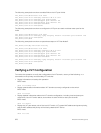
1. Remove the current configuration from the switches. You will need to split the configuration up for
each switch.
2. Copy the files to the flash memory of the appropriate switch.
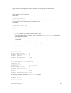
3. Copy the files on the flash drive to the startup-config.
4. Reset the stacking ports to user ports for both switches.
5. Reload the stack and confirm the new configurations have been applied.
6. On the Secondary switch (stack-unit1), enter the command stack-unit1 renumber 0.
7. Confirm the reload query.
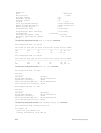
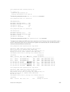
8. After reloading, confirm that VLT is enabled.
9. Confirm that the management ports are interconnected or connected to a switch that can transfer
Heartbeat information.
Specifying VLT Nodes in a PVLAN
You can configure VLT peer nodes in a private VLAN (PVLAN). VLT enables redundancy without the
implementation of Spanning Tree Protocol (STP), and provides a loop-free network with optimal
bandwidth utilization.
Because the VLT LAG interfaces are terminated on two different nodes, PVLAN configuration of VLT
VLANs and VLT LAGs are symmetrical and identical on both the VLT peers. PVLANs provide Layer 2
isolation between ports within the same VLAN. A PVLAN partitions a traditional VLAN into sub-domains
identified by a primary and secondary VLAN pair. With VLT being a Layer 2 redundancy mechanism,
support for configuration of VLT nodes in a PVLAN enables Layer 2 security functionalities. To achieve
maximum VLT resiliency, you should configure the PVLAN IDs and mappings to be identical on both the
VLT peer nodes.
The association of PVLAN with the VLT LAG must also be identical. After the VLT LAG is configured to be
a member of either the primary or secondary PVLAN (which is associated with the primary), ICL becomes
an automatic member of that PVLAN on both switches. This association helps the PVLAN data flow
received on one VLT peer for a VLT LAG to be transmitted on that VLT LAG from the peer.
You can associate either a VLT VLAN or a VLT LAG to a PVLAN. First configure the VLT interconnect (VLTi)
or a VLT LAG by using the peer-link port-channel id-number command or the VLT VLAN by using
the peer-link port-channel id-number peer-down-vlan vlan interface number command
and the
switchport command. After you specify the VLTi link and VLT LAGs, you can associate the
same port channel or LAG bundle that is a part of a VLT to a PVLAN by using the interface interface
and switchport mode private-vlan commands.
When a VLTi port in trunk mode is a member of symmetric VLT PVLANs, the PVLAN packets are
forwarded only if the PVLAN settings of both the VLT nodes are identical. You can configure the VLTi in
trunk mode to be a member of non-VLT PVLANs if the VLTi is configured on both the peers. MAC address
synchronization is performed for VLT PVLANs across peers in a VLT domain.
984
Virtual Link Trunking (VLT)