


xStack DES-3800 Series Layer 3 Stackable Fast Ethernet Managed Switch
34
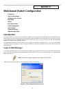
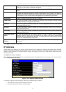
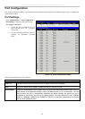
3. To access the Switch from a different subnet from the one it is installed on, click the Modify link next to Default
Gateway and enter the IP address of the Default Gateway. To manage the Switch from the subnet on which it is installed,
leave the default entry in this field.
4. If no VLANs have been previously configured on the Switch, use the default VLAN Name. The default VLAN contains
all of the Switch ports as members. If VLANs have been previously configured on the Switch, users will need to enter the
VLAN ID of the VLAN that contains the port connected to the management station that will access the Switch. The
Switch will allow management access from stations with the same VID listed here.
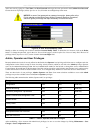
NOTE: The Switch's factory default IP address is 10.90.90.90 with a
subnet mask of 255.0.0.0 and a default gateway of 0.0.0.0.
To use the BOOTP or DHCP protocols to assign the Switch an IP address, subnet mask and default gateway address, use the Get
IP From pull-down menu to choose from BOOTP or DHCP. This selects how the Switch will be assigned an IP address on the
next reboot.
NOTE: If you enable the AutoConfig, the Get IP From setting will
automatically become DHCP.
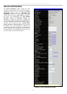
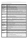
The IP Address Settings options are:
Parameter Description
BOOTP
The Switch will send out a BOOTP broadcast request when it is powered up. The BOOTP
protocol allows IP addresses, network masks, and default gateways to be assigned by a
central BOOTP server. If this option is set, the Switch will first look for a BOOTP server to
provide it with this information before using the default or previously entered settings.
DHCP
The Switch will send out a DHCP broadcast request when it is powered up. The DHCP pro-
tocol allows IP addresses, network masks, and default gateways to be assigned by a DHCP
server. If this option is set, the Switch will first look for a DHCP server to provide it with this
information before using the default or previously entered settings.
Manual
Allows the entry of an IP address, Subnet Mask, and a Default Gateway for the Switch.
These fields should be of the form xxx.xxx.xxx.xxx, where each xxx is a number
(represented in decimal form) between 0 and 255. This address should be a unique address
on the network assigned for use by the network administrator.
Subnet Mask
A Bitmask that determines the extent of the subnet that the Switch is on. Should be of the
form xxx.xxx.xxx.xxx, where each xxx is a number (represented in decimal) between 0 and
255. The value should be 255.0.0.0 for a Class A network, 255.255.0.0 for a Class B
network, and 255.255.255.0 for a Class C network, but custom subnet masks are allowed.
Default Gateway
IP address that determines where packets with a destination address outside the current
subnet should be sent. This is usually the address of a router or a host acting as an IP gate-
way. If your network is not part of an intranet, or you do not want the Switch to be accessible
outside your local network, you can leave this field unchanged.
VLAN Name
This allows the entry of a VLAN Name from which a management station will be allowed to
manage the Switch using TCP/IP (in-band via web manager or Telnet). Management
stations that are on VLANs other than the one entered here will not be able to manage the
Switch in-band unless their IP addresses are entered in the Security IP Management menu.
If VLANs have not yet been configured for the Switch, the default VLAN contains all of the
Switch's ports. There are no entries in the Security IP Management table, by default, so any
management station that can connect to the Switch can access the Switch until a
management VLAN is specified or Management Station IP Addresses are assigned.
Auto Config State When autoconfig is enabled, the Switch is instructed to get a configuration file via TFTP, and
it becomes a DHCP client automatically. The configuration file will be loaded upon booting
up. In order to use Auto Config, the DHCP server must be set up to deliver the TFTP server
IP address and configuration file name information in the DHCP reply packet. The TFTP
server must be running and have the requested configuration file stored in its base directory
when the request is received from the Switch. Consult the DHCP server and/or TFTP server
software instructions for information on loading a configuration file for use by a client.