Stylus Color service
Manual
Appendix
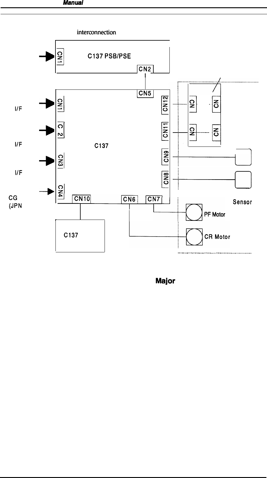
A.1 CONNECTOR SUMMARY
The figure below shows the
intercomection
between the major components of the Stylus Color.
AC Input
Parallel
IIF
Type B
Parallel
IIF
RS-422
Serial
IJF
Option
CG
Board
(JPN
only)
+
+
+
+
1
0
z
C137
PSB/PSE
ICN2
I
Printhead
I
Unit
0
z
Iv
Black
C137
MAIN
I
I
Color
r
C137
PNL
*...........................[...........................
1
0
!
z
. . . . . . . .
-
.
z
u
1
c)
z
.
.
.
.
.
.
.
.
.
.
z
c)
HP
Sensor
r
-1
PE
+-Kl’’”otor
‘ensor
q-cl-tor
Figure A-1. Interconnection of
-
.
.
.
.
-
.
.
.
.
.
.
.
.
.
.
.
.
.
.
.
.
.
.
.
.
.
.
.
.
-
.
.
.
.
.
.
.
.
.
.
.
.
.
.
.
.
.
.
.
.
.
.
.
.
.
Printer Mechanism
(M-4A1O)
Components
Rev. A
A-1


