


Stv/us
Color Service Manual
Opefating
Principles
2.3 OPERATING PRINCIPLES OF THE ELECTRICAL CIRCUITS
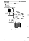
The Stylus Color contains the following circuit board units:
■
C137MAIN Board (Main control circuit board)
■
C137PSB/PSEBoard (Power supply circuit board)
■
C137PNL (Control panel board)
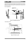
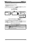
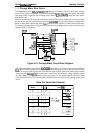
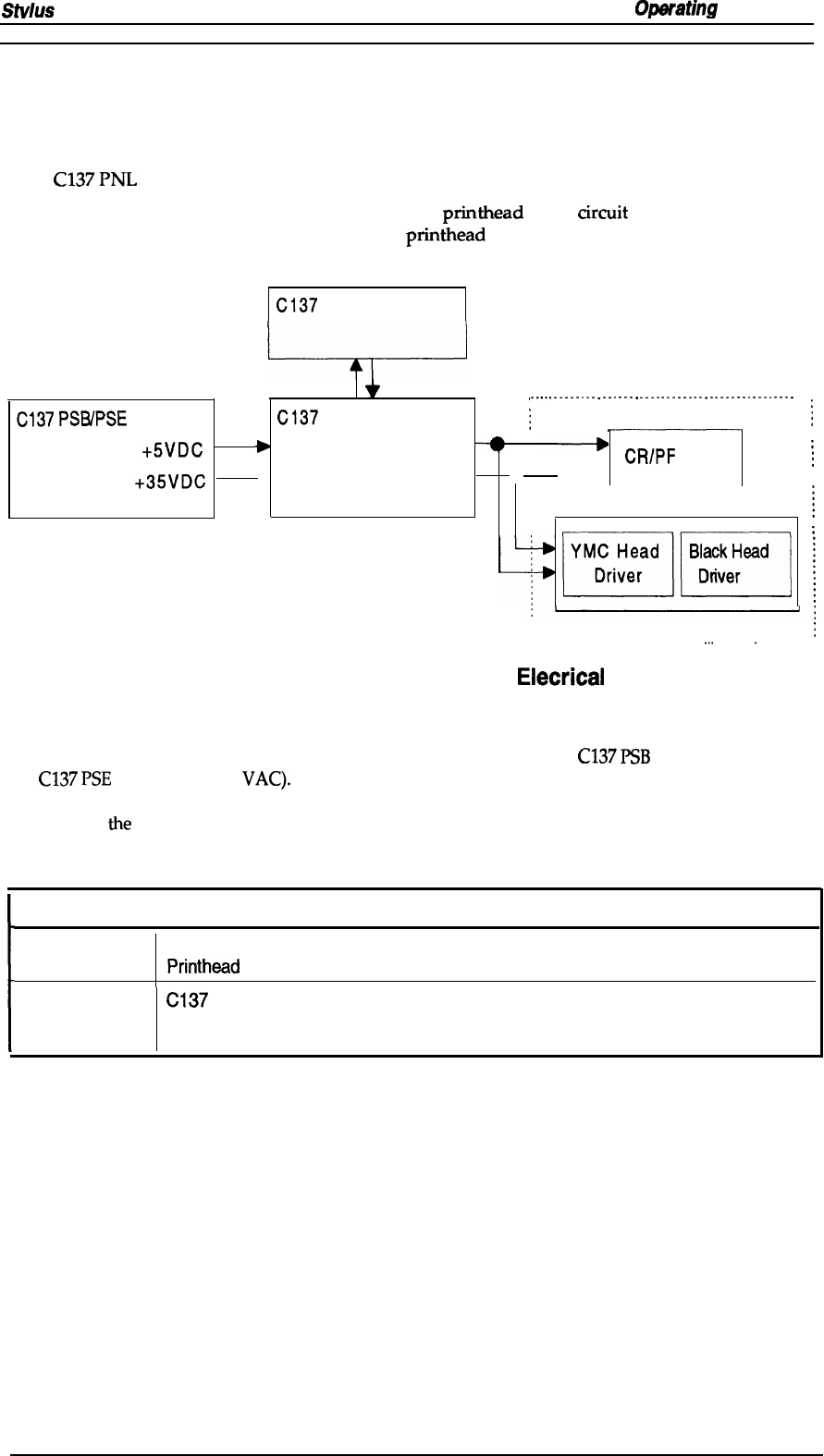
In addition to the circuit boards above, part of the
printhead
drive arcuit is built on a separate
circuit board installed in the carriage unit; the
printhead
is attached directly to this board. The
figure below shows a block diagram of the electrical circuitries.
C137
PNL
,.
..-.
.
.
.
.
.
.
.
.
.
.
.
.
.
.
.
.
.
.
.
.
.
.
.
.
.
.
.
.
.
.
.
.
.
.
.
.
.
.
.
.
.
.
.
.
.
C137
PSB/PSE
C137
MAIN
:
M-4A1O PRINTER MECHANISM
;
+5VDC
>
CR/PF
Motor
j
+35VDC
‘
➤
● -
Carriage Unit
~
~
mm
I
R-T02 Head
R-TOI Head
~
. . . . . . . . . . . . . . . . . . . . . . . . . . . . . .
.
-.
. . . . . . .
.
. . . . . . . . . .
Figure 2-16. Block Diagram of the
Elecrical
Circuit
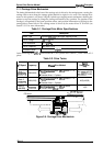
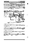
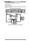
2.3.1 Operating Principles of the Power Supply Circuit
The power supply circuitry for this printer is provided either by the
C137
PSB
board (120 VAC) or
the
C137
PSE
board (220-240
VAC).
Both boards are identical in design and functionality, except for
the components in the primary circuit that accommodate the specified input voltage. The input
voltage and
the
application of output voltages are summarized in the table below.
Table 2-7. DC Voltage Distribution
Voltage
I
Application
Motor drive (carriage and paper feed)
+35 VDC
Printhead
(through the drive voltage generation circuit)
C137
MAIN Board
+5 VDC
Sensors (home position, paper end, no ink cartridge, head thermistor)
Control panel, head nozzle selector
Rev. A
2-13