


Sty/us Color Service Manual
Operating Principles
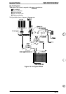
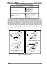
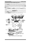
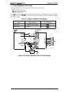
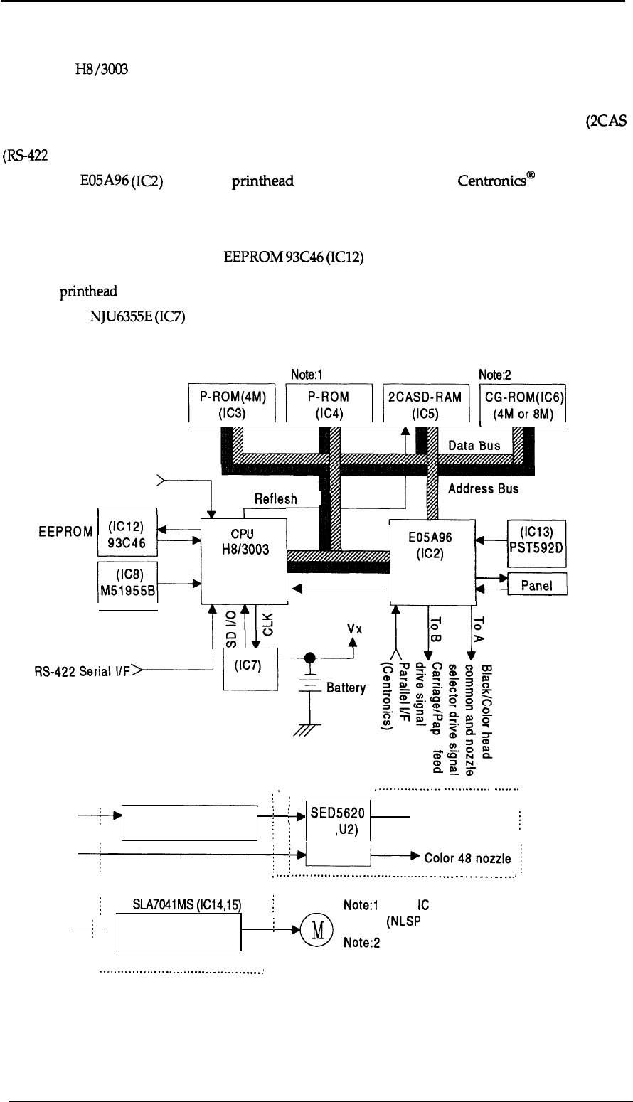
2.3.2 Operating Principles of the Main Control Circuit
The
main control circuit of this printer is the C137 MAIN board. This circuit is controlled by the
16-bit CPU
H8/3003
(ICI), running at 14.7456 MHz. This CPU has a unique architecture capable of
handling data on the data bus at either an 8-bit or 16-bit bus width. Because of this, a 16-bit or 8-bit
data bus width-type ROM is used on this board, increasing the internal processing speed. Also, the
CPU has a unique architecture capable of the refresh control function. A 4M D-RAM
(2CAS
method) on this board is controlled by the CPU itself. The CPU controls the serial interface control
(RS-422
for Mac).
Gate array
E05A96
(IC2)
manages
printhead
drive control, external
Centronics@
parallel I/F,
extension CG board and the control panel, and the controls that create the 4-bit signal for the
carriage or the paper feed motor. (The carriage and paper feed motor are controlled by the current
duty data.)
This board is also equipped with
EEPROM
93C46
(IC12)
to store certain parameters, such as the
printer mechanism control parameter, default setting parameters, as well as a special counter value
used for
printhead
(ink management) protection.
The
timer
IC
NJU6355E
(IC7)
counts each time the printer is cleaned and keeps track of how long
the printer is not used, thereby allowing the printer to be cleared only when necessary.
Note:l
Note:2
mmmm
EEPROM
Reset
(Power)
RS-422
L
1 1
I
I 1
I
I
Type B l/F
I
,7-
I
Reflesh
I
(IC12)
w
I
Pm
i
‘k
%---I=+SSB”L”L
5-
m
93C46
uru
4
E05A96
4
B
(IC13)
H8/3003
(IC2)
PST592D
(IC8)
(lCl)
M51955B
Panel
DMAREQ
I
I
Seria\W#
Cl 37 MAIN Board
. . . . . . . . . . . . . . . . . . . . . . . . . . . . . .
=ery
NJ U6355E
(Timer
Counter)
J
Carriage
. . . . . . . . . . . . . .
.
. . . . . . . . . . . . . . . . . . . . . .
.
CD
.
.
.
.
.
.
.
.
.
.
.
.
.
.
.
.
.
.
.
.
.
.
.
.
.
.
.
.
.
.
.
.
.
.
.
.
.
:
I
:,
From A
~
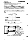
Black/Color head
!
:P
SED5620
➤ Black 64 nozzle
~
Common driver Circuit
\
~
(UI ,U2)
;
----
-----
------
-----
---
--------
----------
.-
.-.
.
.
.
.
.
.
.
.
.
.
.
..-;
[
SLA7041MS(IC14,15)
~
Note:l 32-pin IC socket only
From B
~
●
Carriage/Paper feed
i
@
(NLSP and European ver. only)
Motor Driver
Note:2 8M is only equipped in NLSP ver.
.
.
-.
.
.-
.
.
.
.
.
.
-.
.
.
.
.-
.
-.
.
.
.
-.
.
.
.
.
.-
.-
.
.
.
.
-.
.
.
.,
Figure 2-18. Main Control Circuit Block Diagram
Reset
(Logic)
Rev. A
2-15