


Stylus Color Service Manual
Opefating
Principles
2.2.2
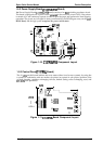
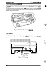
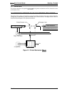
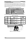
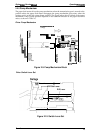
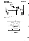
Carriage Drive Mechanism
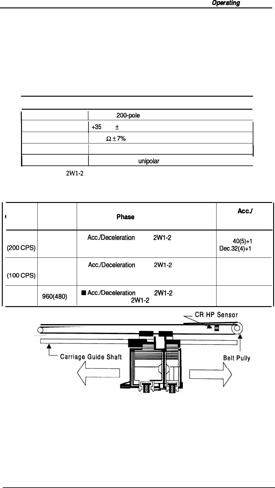
The timing belt attached to the base of the carriage unit is driven by the carriage motor, causing the
carriage unit to move along the carnage guide shaft left to right, or vice versa. The carriage drive
motor on this printer is a 4-phase, 200-pole, hybrid-type stepping motor mechanism, allowing the
printer to stop the carriage or change the carriage movement at any position. The position of the
carriage is recognized by the home position sensor, and position information is fed back to the
carriage drive control circuit. This carriage motor is driven by the motor driver IC SLA7041 (see
Section 2.3.2.3 for more information).
Table 2-1. Carriage Drive Motor Specifications
I
Item
I
Description
I
Motor Type
I
4-phase/
20C)-pole
hybrid-type stepping motor
I
Drive Voltage
+35 VDC
t
5?40
Coil Resistance’
10.0
Q
f
7940
Drive Frequency
960-4800 PPS
Excitation Mode
I
Constant current
unipdar
Drive, Micro Step Driving
I
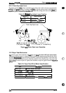
In the following table,
2W1-2
phase means the 1/8 2-2 phase drive control. ( ) is the value of 2-2
phase.
Table 2-2. Drive Terms
ACCJ
CR Speed
Frequency
Phaee
Drive Method
Deceleration
Step
Mode 1
■
Acc./Deceleration
Area: 2WI-2 phase + 1-2
~200
~ps)
4800(2400) phase
Ace.
40(5)+1
10(55)
■
Constant Area: 1-2 phase
Dec.32(4)+1
12(56)
Mode 2
■
Acc./Deceleration
Area: 2WI-2 phase + 1-2
(loo Cps)
2400(1200) phase
40(5)+40(20)
■
Constant Area: 1-2 phase
Mode 3
Q
Acc./Deceleration
Area: 2WI-2 phase
(40 CPS)
‘60(480)
■
Constant
Area:
2W1-2
phase
16(2)
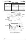
CR Motor
, . . . .
klul
c)
Figure 2-5. Carriage Drive Mechanism
Rev. A
2-5