


Disassembly and Assembly
Stylus Color Service
Mknual
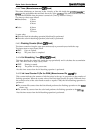
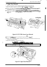
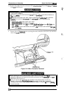
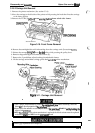
5. Discomect the cables
from
the connectors
CN5,
CN6,
CN7,
CN8,
CN9, CN1O,
CN1l,
and
CN12
of the
C137
MAIN board.
+’-
‘!.
4.
■
When you replace
the
main board, initialize the
EEPROM
contents as follows;
1) Reassemble the printer.
2)
Turn the
pn”nter
ON while hold down
IAltJ,
[Font],
ILoadlEject]
and [Pause] buttons on
the
control panel.
■
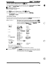
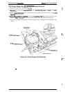
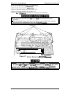
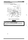
It
is possible to disconnect the cables. When reconnecting the cablesfiom the connectors
CN6,
CN7
and connectors CNII,
CN12
of the C137MAIN board, see the following
instructions.
1.
CN1l:
Printhead
FFC
cable (white color mark)
CN12:
Printhead
FFC
cable (blue color
mark)
2.
CN6
: Carriage motor cable
(red
color mark :Also theredcolor indicates
thel-p”n
of the
CN6J
CN7: Paperfeed motor cable (black color mark
:Also
the black color indicates
thel-pin
of the
CAV.)
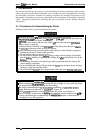
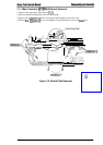
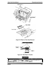
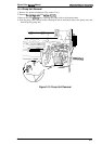
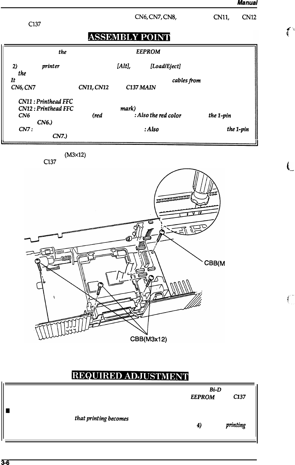
6.
Remove the 4 CBB
(M3x12)
screws securing the main controller to the lower case and then
remove the
C137
MAIN board.
3x
L
’12)
I
Figure 3-6. Main Controller Removal
■
When replacing the main controller board, adjust both the head gap and the
Bi-D
adjustment alignment, and input the destination parameter into the
EEPROM
on the
C137
MAIN Board. (See
Chapter 4.)
H
When you replace
the main board, the parameters in the internal timer are all reset.
Therefore, it is possible
thatprintingbecomes
abnormally. At this time, perform the
cleaning operation by the control panel on command (Refer
to Chapter
4)
until the p“nting
becomes normally.
I
3+
Rev. A