


Stylus Color Service Manual
Product Description
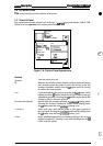
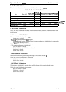
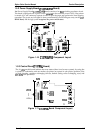
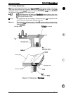
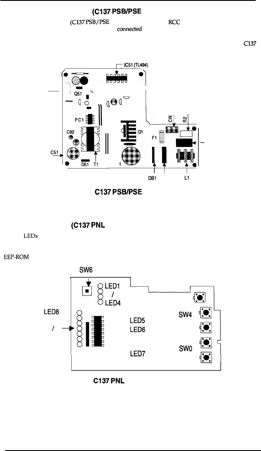
1.5.2 Power Supply Board
(C137
PSB/PSE
Board)
The
Power Supply Board
(C137
PSB/PSE
Board) consists of an
RCC
switching regulator circuit.
This board is equipped with a power switch
comected
to the secondary circuit. Thus, if the printer
is turned off, it can continue to operate in order to eject the paper and perform the head capping
operation. The power on/off signal is always monitored by the E05A96 gate array on the
C137
MAIN Board,
and the logic system
recognizes the power switch status.
j--
IC51
(TL494)
CN2 ,
c~
:-
n
I
;
Q51
. .
J
–Qo
aa
(@r
u
I
cl
,
1-
1-
—
DB1
C3
L1
–
cl
Figure 1-10.
C137
PSB/PSE
Component Layout
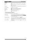
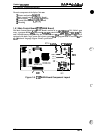
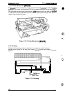
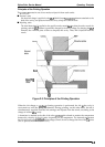
1.5.3 Control Panel
(C137
PNL
Board)
The 14
LEDs
on this board indicate the error status (there is no buzzer system); by using the
6 switches in combination with one another, the printer can operate in each protect operation (color
or black cleaning, cartridge exchanging self-test, default setting value exchanging, reset, and
EEP-ROM
clear operation).
SW6
t
t
LED8
/-
LED14
q
LED1
❑
/
LED4
[It
0
0
0
1---1
I
LED5
LED6
I
m7
SW4
Ill
M
● 0
/
‘0
i-l
:0°
Swo
‘
m
—
n
I
Figure 1-11.
C137
PNL
Board Component Layout
Rev.
A
1-19