


Disassembly and Assemb/y
Stylus Color Service
Mi3nual
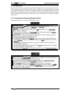
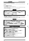
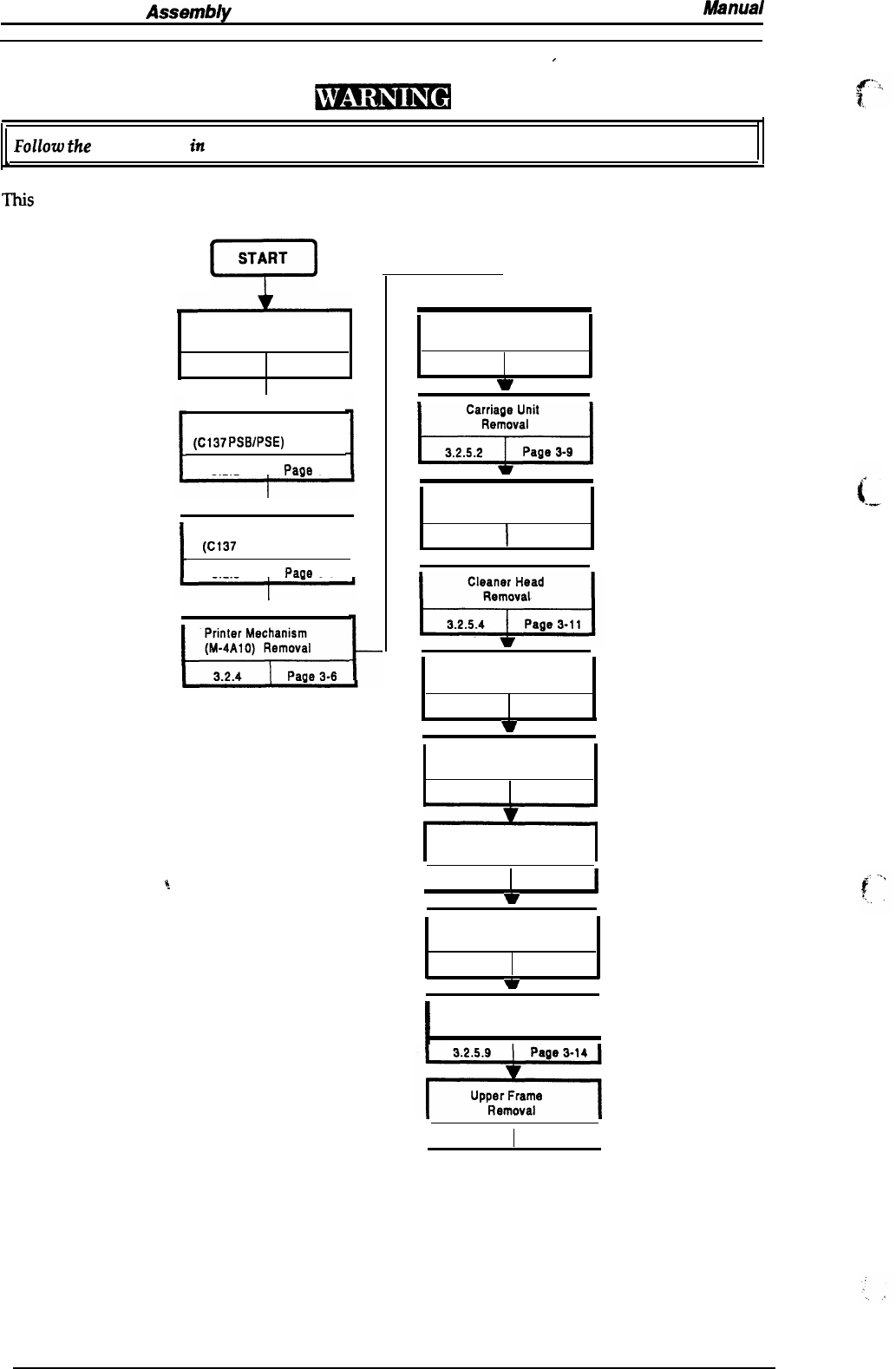
3.2 DISASSEMBLY AND ASSEMBLY
/
Follow
the
precautions
in
Section 3.1.1 when disassembling the printer.
b
,
TMS
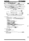
section consists of the subheads shown in the diagram below. See the exploded view of the
printer in the Appendix, if necessary.
P
START
Upper Case Removal
3.2.1
Page
3-3
Power Supply Unit
(C137 PSB/PSE) Removal
3.2.2
I
Paae 3-4
I
Main Controller
(C137 MAIN) Removal
I
t
393
I
Paae
3-5
1
I%!!??&
Printhead Unit
Removal
3.2.5.1
Page 3-7
*
w
Pump Unit
Removal
3.2.5.3
I
Page 3-10
7
CR Motor
Removal
3.2.5.5
Page 3-12
w
i
-.
I
3.2.5.7
Page
3-13
w
PF
Motor
Removal
3.2.5.6
Page
3-12
Carriage
Home Position
Sensor Removal
PE Sensor
Removal
3.2.5.8
Page 3-13
w
I
I
PF Roller Assembly
Removal
I
I
3.2.5.10
Page 3-15
I
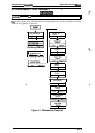
Figure 3-1. Disassembly Flowchart
3-2
Rev. A