


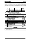
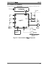
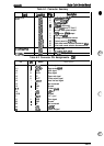
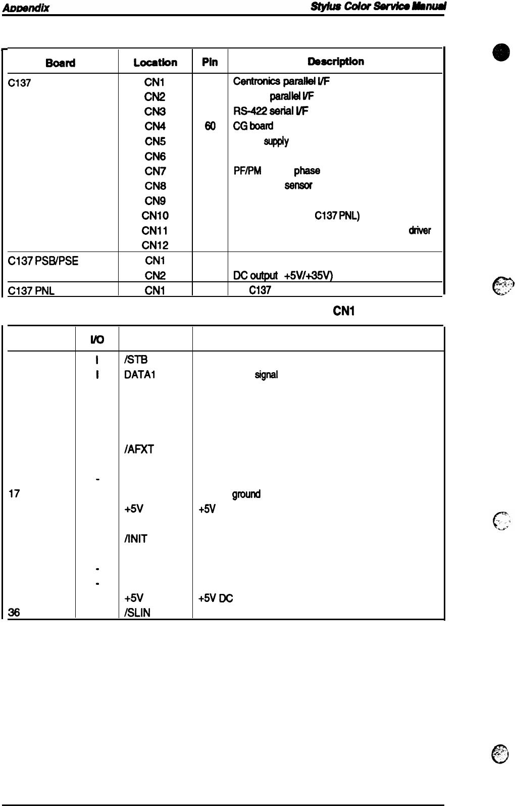
Table A-1. Connector Summary
Board
Locatfon
Pin
OOecri@On
C137
MAIN
CN1
36
Cerltronics
paratlel
I/F
CN2
36
Type B
paralld
W
CN3
8
RS-422
eerial
I/F
CN4
60
CG
bard
(JPN only)
CN5
6
Power
eupply
from
PS board
CN8
5
carriage motor phase output
CN7
5
PIWM motor
phaee
output
CN8
2
Paper end
Seneor
CN9
3 Carriage home position sensor
CN1O
20
Control panel (to
C137
PNL)
CN1l
22
Black head nozzle selector &common
ddver
CN12
22
Color head nozzle selector &common driver
C137
PSB/PSE
CN1
2
AC inlet (L/N)
CN2
8
Dcoutput
(
+5VH5V)
C137
PNL
CN1
20
(to
C137
MAIN)
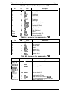
Table A-2. Connector
Pin Assignments -
CN1
Pin
w
Name
Description
1
I
IN-B
Strobe
signal
2-9
I
DATA1
-8
Data strobe
eignal
10
0
/ACK
ACK signal
11
0
BUSY
Busy signal
12
0
PE
Paper end signal
13
0
SLCT
Printer select signal
14
I
IAFXT
Auto line feed signal
15
.
NC
Not connected
16
-
GND
Ground
17
FG
Frame
ground
18
.
+5V
+5V
DC
19-30
.
GND
Ground
31
I
flNIT
INIT signal
32
0
/ERR
Error signal
33
-
GND
Ground
34
-
NC
Not connected
35
+5V
+5V
Dc
36
I
/SLIN
Select in signal
A-2
Rev. A