


Sty/us
Color
service
Manual
Operating Principles
2.3.2.3
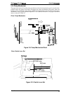
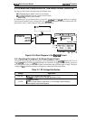
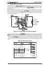
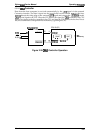
Carriage Motor Drive Circuit
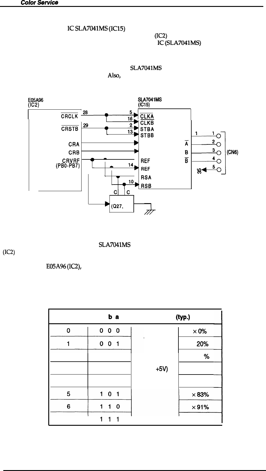
The carriage motor drive
IC
SLA7041MS
(IC15)
outputs a constant current to drive the carriage
motor for the printer mechanism. Gate array E05A96EA
(IC2)
decides the motor phase
and speed
and then sends a signal to the carriage motor driver
IC
(SLA7041MS)
using the 4-bit serial
transmission line.
The first bit indicates the direction of the motor rotation. The other three bits are current duty data
for the motor speed of each printing sequence.
SLA7041MS
can select the reference voltage itself
based on these three current duty data.
Also,
it receives these signals by 2 serial transmission lines
for 2 motor’s phases (phase A and phase B). Due to this, the carriage motor can drive the miao step
sequence (min. 1/720 inches).
E05A96
SLA7041MS
(IC2)
(IC15)
CRCLK
28
~
CLKA
m
9?
‘
CLKB
CRSTB
‘“
m
. —
STBA
13*
—
*
STBB
A
‘
1
27
6
CRA
b
DATA A
K 82
25
17
CRB
*
DATA B
~
11 3
CRVRF
B
a
3
➤
REF
A
B
18 4
(PBO-PB7)
A
14
*
REF
B
>
m
5
CRHLD
—
L
9
m
+
4
w
●
RSA
RSB
B
NPN Tr
E
b
(Q27,
28)
(CN6)
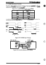
Figure 2-21. Carriage Motor Circuit Block Diagram
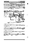
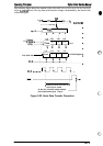
The 4-bit serial data is read by the
SLA7041MS
motor driver by 4 clock counts from the E05A%
(IC2)
clock. Each bit is read by the falling edges of these clock pulses. Due to this, the received serial
data is set into the shift register and then shifts the latch register. When the strobe pulse becomes
active from the
E05A96
(IC2),
the serial data is moved into the reference voltage selection circuit
and the voltage is changed. Therefore, when the printer is in the constant speed mode, this strobe
pulse becomes inactive. The following table indicates the current duty of each carriage motor speed
mode.
Table 2-8. Serial Data Contents
Mode
I
c
ba
I
Vref
(typ.)
*“
‘w’
x
20?/$0
2
010
x 40 %0
Vref x 1/3
3
011
(Vref =
+5V)
x 55.5?/0
4
100
x 71.470
7
I
111
I I
x 100%
Rev. A
2-17