


EPSON Stylus Photo 750 Revision A
Appendix Connector Summary 97
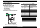
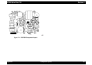
7.1 Connector Summary
7.1.1 Major Component Unit
Major component unit of this printer is as follows.
† Control Board (C259 MAIN or C264 MAIN)
† Power Supply Board (C257 PSB/C257 PSE)
† Control Panel (C209PNL)
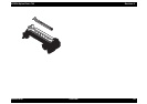
† Printer Mechanism (M-4M11)
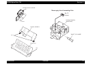
The figure below shows how these components are connected.
Figure 7-1. Connection of the Major Components
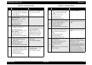
Table 7-1. Connector Summary for C259Main
Table 7-2. Connector CN4
CN1
CN2
AC
CN10
CN11
CN9
C259/C264MAIN
(Main Board)
CN1
CN2
CN7
CN8
CN6
CN14
CN5
Control Panel
Print Head
CR
Motor
PF
Motor
ASF Sensor
HP Sensor
PE Sensor
Parallel I/F
Printer Mechanism
C206PSB/PSE
(Power Supply
Board)
Serial I/F
Cartridge Sensor
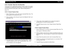
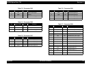
Connector Function Table to refer.
CN1
Parallel Interface
Connector
Parallel Interface(forward channel)
(See page -14)
CN2
Mac.Serial Interface
Connector
Serial Interface
(See page -18)
CN3 SUB Interface Connector
USB(Universal Serial Bus) interface
(See page -19)
CN4 HP Sensor Table7-2
CN5 PE Sensor Table7-3.
CN6 ASF Sensor Table7-4
CN7 CR Motor Table7-5
CN8 PF Motor Table7-6
CN9 Print Head Table7-7
CN10 Power Supply Connector Table7-8
CN11 Control Panel Table7-9
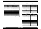
Pin Signal Name I/O Function
1 HP In Sensor detect signal
2 GND --- Ground
3 HPV --- Sensor Power Supply