


EPSON Stylus Photo 750 Revision A
Disassembly and Assembly Disassembly 56
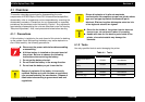
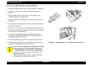
CHECK
POINT
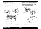
Unlock the connector CN6 and CN7 before
disconnecting them. Also, be sure to lock them when
reconnecting them.
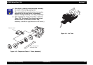
ADJUSTMENT
REQUIRED
After replacing C259 Main Board, perform the
following adjustments.
1. Head ID Writing (See “Head Voltage ID
Adjustment” on page -83)
2. Head Angular Adjustment (See “Head Angular
Adjustment” on page -84
3. Bi-D Adjustment (See “Bi-D Adjustment” on
page -86)