


EPSON Stylus Photo 750 Revision A
Operating Principles Operating Principles of Electric Circuit 34
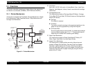
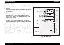
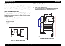
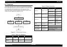
2.2.2.3 Sensor Circuit
The following sensor circuits are mounted on the C259 Main Control
Circuit.
† HP Sensor
HP sensor uses the photo interrupter method. A HP sensor detects
the carriage home position. It is used for managing printing position
and cleaning, etc.
† PE Sensor
PE sensor uses the photo interrupter method. A PE sensor
determines if there is a paper in the printer. Based on the signal
from this sensor, a particular page edge treatment such as Micro-
weave printing is performed.
† ASF Sensor
ASF sensor uses the photo interrupter method. An ASF sensor
detects the position of return lever when the power is turned on, and
causes the paper to be picked up by the pick up roller fro the normal
initial position.
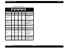
† Thermistor Sensor (TH)
This sensor is mounted on the print head board and measures the
temperature around the head. It keeps stable printing quality,
changing PZT drive voltage(VH) slightly according to changes of
environmental temperature.
† Black/Color Cartridge Sensor(COB/COC)
Cartridge sensor uses the mechanical method. The sensor detects
if the cartridge is installed or not.
Figure 2-6. Sensor Circuit
coc
+5V
+5V
CN4
CN5
CN6
ASF
HP
PE
PE
GND
PEV
HP
GND
HPV
ASF
GND
ASFV
+5V
+5V
+5V
+5V
+5V
+5V
+5V
97
SWA0
98
SWA1
99
SWA2
IC 2
E05B58**
op06
CPU
CN9
COB
GND
THM
SWC0
SWC1
AN0