


EPSON Stylus Photo 750 Revision A
Operating Principles Operating Principles of Electric Circuit 31
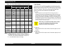
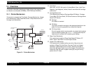
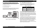
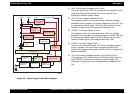
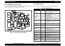
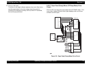
Figure 2-3. Power Supply Circuit Block Diagram
† +42V Line Constant Voltage Control Circuit:
The output level of the +42V line is monitored by a detection circuit
consisting of seven Zener diodes.This circuit prevents from
dropping for constant output voltage.
† +5V Line Over Voltage Protection Circuit:
This protection circuit is in the same line as +42V over voltage
protection circuit is located. The output voltage level of the +5V line
is monitored by a Zener diode. This circuit shuts down the circuit
operation forcefully when the voltage level exceeds +9V.
† +42VDC Line Drop Limitation Circuit:
This protection circuit is in the same line as +42V over voltage
protection circuit is located. The output voltage level of the +42V line
is monitored by a Zener diode. This circuit shuts down the circuit
operation forcefully when the voltage levels drops +36V.
† +42VDC Line Over Voltage Circuit:
This circuit is in the same line as +5V line over voltage protection
circuit is installed. The output level is monitored by two Zener
diodes. If the voltage level exceeds +48VDC, this circuit stops circuit
operation forcefully.
† +5V Line Constant Voltage/Constant Current Control Circuit:
The output current is monitored by a +5VDC generation switching
control IC(IC51), which also monitors the output voltage. This
information is input to the internal comparator and stabilizes +5V
line.
F1
C11
L1,R1-2
C1-C4
DB1
TRANS(T1)
Over Current
Protection
Filter Circiut
Full Wave
Rectifier circuit
Smoothing
Circuit
Main Switching
Circuit
Q1
Abnormal
Feed back circuit
Q2,Q3,Q31
Photo
Coupler
PC1
D51
AC Input
Smoothing
Circuit
C51
+42VDC Line
Constant Control
ZD81-86,ZD51
Power Drop
Delay Circuit
C84,Q84
+42VDC Line
Over Voltage
Limitation
ZD52,87
+5V Regulator
IC51
+42 VDC
+5 VDC
+5VDC Line
Over Voltage
Limitation
PSC Signal
from Main board
ZD53
+42VDC Lin Drop
Limitation Circuit
ZD90
op03