


EPSON Stylus Photo 750 Revision A
Product Description Parallel Interface 18
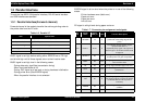
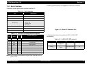
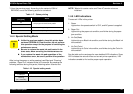
1.3.3 Serial Interface
This section shows specification for serial interface I/F.
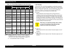
Table 1-11. Serial interface
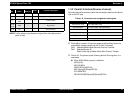
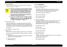
Table 1-12. Connector pin assignment and signals
NOTE: In/Out refers to the direction of signal flow from the printer’s
point of view.
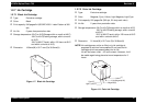
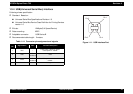
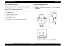
Following figure shows port arrangement of serial I/F connector.
Figure 1-10. Serial I/F Connector Port
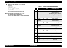
Following table shows timing relation of DTR, X-ON/X-OFF
handshaking.
Table 1-13. X-ON/X-OFF, DTR protocol
Item Specification
Standard Based on RS-423
Synchronization Synchronous
Bit rate Approx. 1.8Mbps
Word format
• Start bit 1bit
• Data bit 8bit
• Parity bit none
• stop bit 1bit
Handshaking X-ON/X-OFF, DTR protocol
Adaptable connector 8-pin mini circular connector
Recommended interface cable Apple System Peripheral-8 cable
Pin
No.
Signal
Name
In/Out Function Description
1 SCLK Out Synchronous clock
2 CTS In Clear to send
3 TxD- Out Transmitt data-
4 S.G. In Signal ground
5 RxD- In Receive data-
6 TxD+ Out Balanced Transmit+
7 DTR Out Data terminal ready
8 RxD+ In Balanced Receive+
State Buffer space X-on/X-off DTR
Busy
Less than 3072
bytes
Send X-OFF code Off
Ready
More than 5120
bytes
Send X-ON code On