


EPSON Stylus Photo 750 Revision A
Disassembly and Assembly Disassembly 64
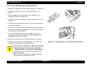
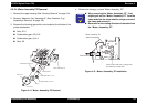
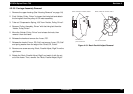
4.2.5.4 Motor Assembly PF Removal
1. Remove the upper housing.(See “Housing Removal” on page -54)
2. Remove “Absorber Tray, Assembly;A”. (See “Absorber Tray,
Assembly;A Removal” on page -58)
3. Remove the following gears which are located at the left side of the
printer mechanism.
„ Gear, 67.2
„ Combination gear, 8.8,21.6
„ Combination gear, 8,14.4
„ Gear, 36
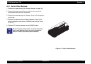
Figure 4-14. Motor, Assembly, PF Removal
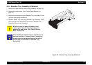
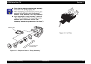
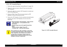
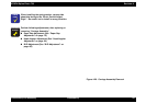
4. Remove the hexagon nut and ”Motor, Assembly, PF”.
Figure 4-15. Motor, Assembly, PF Installation
M o to r, A sse m b ly, P F
Hexagonal Nut
Com pression Spring, 0.9
Gear, 67.2
Lock R ing
Gear, 36
Com bination Gear, 8.8, 21.6
Com bination Gear, 8, 14.4
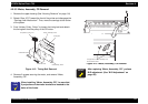
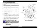
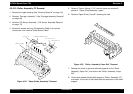
CHECK
POINT
„
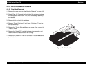
When removing the “Motor, Assembly, PF”, first,
slightly pull out the “Motor, Assembly, PF” from the
frame and slide the motor shaft to a larger cut out of
the frame and remove it.
„
Be careful for the routing direction of the cable from
the “Motor, Assembly, PF”.
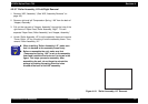
Motor, Assembly, PF
(behind the fram e)
Cable Direction
Put the m otor shaft once in a larger hold
then slide it to a sm aller hole