


EPSON Stylus Photo 750 Revision A
Disassembly and Assembly Disassembly 63
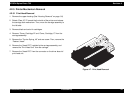
4.2.5.3 Motor, Assembly, CR Removal
1. Remove the upper housing.(See “Housing Removal” on page -54)
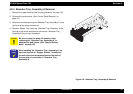
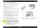
2. Rotate “Gear, 67.2” toward the front of the printer and disengage the
“Carriage Lock Mechanism”. Then, move the carriage to the center
of the platen.
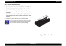
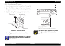
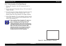
3. Push “Holder, Pulley, Driven” to loosen the timing belt and detach
the timing belt from the pulley of the CR motor.
Figure 4-12. Timing Belt Removal
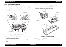
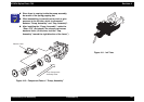
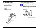
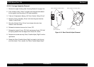
4. Remove 2 screws securing the motor, and remove “Motor,
Assembly, CR”.
Figure 4-13. Motor, Assembly, CR Removal
CHECK
POINT
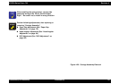
When installing “Motor, Assembly, CR”, be sure that
2 projections of the motor bracket are inserted to the
holes of the frame.
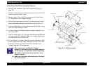
Conpression, Spring, 19.6 Pulley, Assem bly, Driven
Tim ing Belt
O uts id e sid e fra m e
In sid e sid e fra m e
Holder, Pulle
y
, D rive n
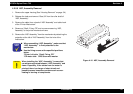
ADJUSTMENT
REQUIRED
After replacing “Motor, Assembly, CR”, perform
Bi-D adjustment. (See “Bi-D Adjustment” on
page -86)
The projections of m otor assem bly m ust
lo ca te in sid e th e h o le s